

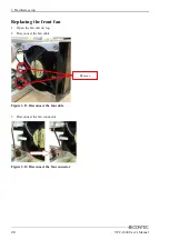


3. Hardware setup
38
VPC-1600 User’s Manual
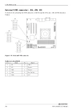
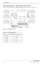
COM port connector : J24, J25, J28, J29, J36, J37
These are connected to the COM1, COM2, and COM3 connectors at the rear of the main unit.
Figure 3.24 COM port connector
Table 3.14 J24,J25,J28,J29,J36,J37
RS-232C
Pin
Signal
Pin
Signal
1
DCD
6
CTS
2
DSR
7
DTR
3
RXD
8
RI
4
RTS
9
Ground
5
TXD
10
NC
Summary of Contents for VPC-1600
Page 1: ...FA Computer Space Saving Model VPC 1600 User s Manual CONTEC CO LTD...
Page 15: ...1 Before Using the Product 8 VPC 1600 User s Manual...
Page 21: ...2 System reference 14 VPC 1600 User s Manual...
Page 49: ...3 Hardware setup 42 VPC 1600 User s Manual...
Page 69: ...4 BIOS setup 62 VPC 1600 User s Manual...
Page 97: ...6 Software RAID Setup 90 VPC 1600 User s Manual...