2. Module Nomenclature and Settings
ADI16-4(FIT)GY
9
2.
Module Nomenclature and Settings
Nomenclature of Module Components
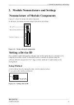
Figure 2.1. shows the names of module components.
In the figure, the indicated switch settings represent factory settings.
Figure 2.1. Names of module components
Setting a Device ID
The controller module distinguishes and keeps track of the modules that are connected to it by
assigning device IDs to them. Each module, therefore, should be assigned a unique ID.
A Device ID can be assigned in a 0 to 7 range, so that a maximum of eight modules can be
distinguished.
Setup Method
A device ID can be set by turning the rotary switch on the device face.
To set a device ID, turn the switch knob.
Figure 2.2. Setting a Device ID
Device ID
Interface Connector
Range Setting Switches
CH0
CH1
CH2
CH3
+
-
AG
+
-
AG
+
-
AG
+
-
AG
Device
ID
0
4
0
4
6
2
5
1
3
7
Factory settings:
(Device ID = 0)


