3. External Connection
DIO-48D-LPE
27
3.
External Connection
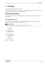
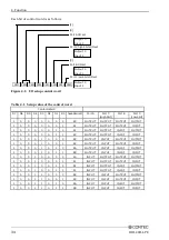
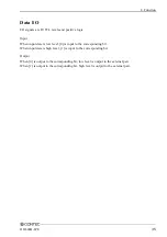
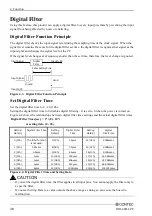
This chapter describes the interface connectors on the board and the external I/O circuits.
Check the information available here when connecting an external device.
How to connect the connectors
Connector shape and optional cable connection
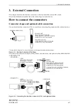
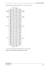
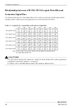
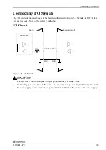
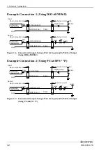
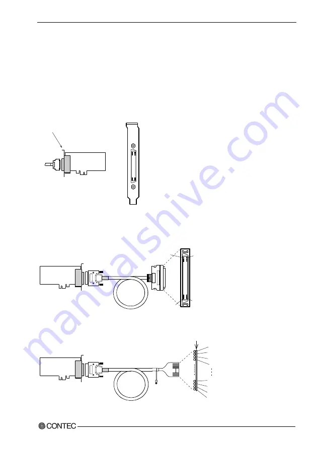
The on-board interface connector (CN1) is used when connecting this product and the external devices.
- Connector used
68-pin 0.8mm pitch connector
HDRA- [HONDA TSUSHIN
KOGYO CO., LTD.] or equivalent
- Compatible connector
HDRA-E68MA1 [HONDA TSUSHIN
KOGYO CO., LTD.] or equivalent
Interface connector (CN1)
* Please refer to chapter 1 for more information on the supported cable and accessories.
Figure 3.1. Interface Connector (CN1) Shape
This shows the connection example of this product, external device and optional cables (DIO-68M/96F
or PCA68PS-**P)
- [ ] shows the pin No. of HONDA TSUSHIN
KOGYO CO., LTD. specification.
Laminate side
15
0m
m
1
35
2
36
33
67
34
68
B01[96]
A48[1]
B48[49]
A01[48]
- Connector used
96-pin half-pitch, female connector
PCR-E96FB [HONDA TSUSHIN
KOGYO CO., LTD.] or equivalent
- Cable
68conductor Shield cable
Cable length : 500mm
Conductor size : AWG#30
- Cable
68conductor Shield cable
Cable length : PCA68PS-0.5P 500mm
PCA68PS-1.5P 1500mm
Conductor size : AWG#30
<DIO-68M/96F>
<PCA68PS-**P>
Figure 3.2. Connecting the interface connector (CN1) and optional cables
Summary of Contents for DIO-48D-LPE
Page 7: ...vi DIO 48D LPE ...
Page 15: ...1 Before Using the Product 8 DIO 48D LPE ...
Page 33: ...2 Setup 26 DIO 48D LPE ...
Page 45: ...4 Function 38 DIO 48D LPE ...

