6. Appendix
74
BX-320 User’s manual
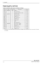
Interrupt Level List
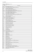
Table 6.2. Hardware Interrupt Levels (Factory Settings)
Type
8259
Priority
Description
Vector
IRQ0
MASTER
High
Timer 0
08H
IRQ1
”
↑
System reserved
09H
IRQ2
”
Interrupt controller 2 (slave)
0AH
IRQ8
SLAVE
Real-time clock
70H
IRQ9
”
System reserved
71H
IRQ10
”
F&eIT
device
72H
IRQ11
”
System reserved
73H
IRQ12
”
F&eIT
device
74H
IRQ13
”
Co-processor
75H
IRQ14
”
IDE
76H
IRQ15
”
System reserved
77H
IRQ3
MASTER
Serial port 2 (COM2)
0BH
IRQ4
”
Serial port 1 (COM1)
0CH
IRQ5
”
F&eIT
device
0DH
IRQ6
”
↓
System reserved
0EH
IRQ7
”
Low
F&eIT
device
0FH
*
Interrupt is a list of states that do not use the APIC. As Windows uses the APIC, PCI device interrupts are allocated
after IRQ16.
Summary of Contents for BX-320-DC700000
Page 1: ...IPC Series BOX PC for BX 320 Series User s Manual CONTEC CO LTD...
Page 7: ...vi BX 320 User s manual...
Page 21: ...2 System Reference 14 BX 320 User s manual...
Page 61: ...4 BIOS Setup 54 BX 320 User s manual...
Page 77: ...5 Each Component Function 70 BX 320 User s manual...


