USER MANUAL
QU-CM-5510/-2
MOTORIZEDCARD READER MODULE
Page 1 of 9
Page 1: ...USER MANUAL QU CM 5510 2 QU CM 5510 2 MOTORIZEDCARD READER MODULE Page 1 of 9 ...
Page 2: ...art combination makes product with fresh appearance and its precision meets or overpass the same product all over the world Excellent circuit design takes multiple protection functions into consideration It is a card reading equipment that can read or write many types of cards supporting 8 pieces SIM card operation Model Name Rules Card Type Model Name IC Card R W Mag Card RFID Card R W Encryption...
Page 3: ...rotection in negative direction Not above 40V Ⅲ PARAMETERS DC 12 V MAX CURRENT 3A Static current 100mA Recommend 12V 3A Operation Power Operation Te mp Humi 0 50 30 90 Relative Humidity RS232 serial port Support 2400 38400BPScommunication rate Interface Card width 54 0 5mm Card size Card length 85 0 5mm Card thickness 0 2 2 0mm Card material Weight Paper card or polyester card about 1 3kg Magnetic...
Page 4: ...ble 4PIN 3PIN 3PIN Communication Interface RS232 4 PIN DC12V POWER Interface Rear of the Machine RS232 Interface DB9 to computer serial port 3PIN RS232 Socket The other port of theMachine Rear T RS232 Cable RS232 ZIP Input Requirement RS232 CABLE PIN NO TO TO PC 1Pin Right TXD 3PIN CONN RS232 level RS232 level 2Pin Middle RXD 3Pin Left GND Connect with Ground Page 3 of 9 ...
Page 5: ...nterface POWER CABEL TO DC12V POWER TO MACHINE POWER SOCKET POWER ZIP PIN NO INPUT REQUIREMENT PIN 2 3 GND Connect with Ground Black Wire VCC DC12V Current over 1 5A PIN 1 4 Red Wire Power cable connector DC12V 5 DNG DNG DC12V 5 Page 4 of 9 ...
Page 6: ...USER MANUAL QU CM 5510 2 Page 5 of 9 ...
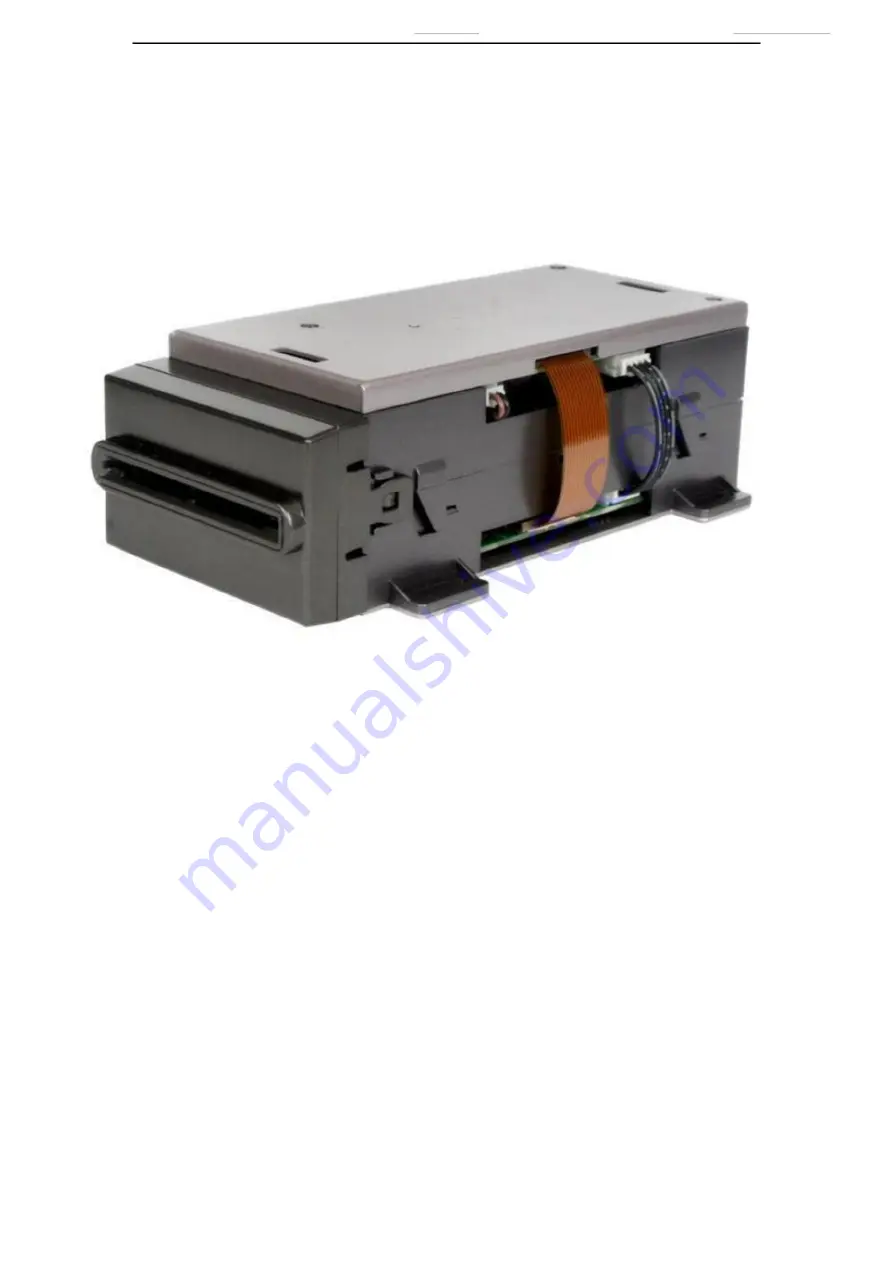
Page 7: ... QU CM 5510 2 Ⅴ COMPONENTS AND PARTS INTRODUCTION Top Part of the Main Body Top Cover Front transmitting wheel Another Part of the Main Body Card Bezel series Back transmitting wheel Transmitting belt Page 5 of 9 ...
Page 8: ... card as picture indicated Contact IC card Hold the card the chip IC at the front of the card to insert as picture indicated Non contact IC card Both side and direction is available for reading and writing CARD INSERT DIRECTION AS BELOW Chip IC CARD Non contact IC Magnetic Card magnetic stripe at the other side Page 6 of 9 ...
Page 9: ...USER MANUAL QU CM 5510 2 Ⅶ INSTALLATION AND STRUCTURE DRAWING Page 7 of 9 ...
Page 10: ...ar the end away from chip should be inserted into card reader first c When inserting RF card directions are not considered But it can only be operated at RF position 5 When there is card in the machine error message will be given if inserting card again And motor door will not open 6 7 When shutting off power power interface should be shut off first then communication interface Power off during op...
Page 11: ... covered with dirt d Should disassembly card reader and clean it drawing 2 Magnetic head maintenance Use cleaning card to clean magnetic head in card reader 3 Detecting pin contact maintenance Dirt on the detecting pin of IC card makes machine not connect well with IC card chip You should disassembly machine to clean it Please refer to disassembly method drawing 4 Gear maintenance Check gear perio...