


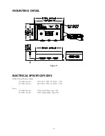


-7-
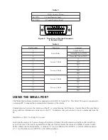
Figure 6 - Rear View of Switchover Connector
Figure 7 - Rear View of Input Connector to
Remote Alarm
SYSTEM
Switchover
Connector
Pin #
Remote Alarm
Connector
Pin #
Function
1
LEFT BANK
1
3
+12
2
15
LBSW status
RIGHT BANK
3
14
RBSW status
4
16
Gnd
2
LEFT BANK
1
6
+12
2
18
LBSW status
RIGHT BANK
3
17
RBSW status
4
19
Gnd
3
LEFT BANK
1
9
+12
2
21
LBSW status
RIGHT BANK
3
20
RBSW status
4
22
Gnd
4
LEFT BANK
1
12
+12
2
24
LBSW status
RIGHT BANK
3
23
RBSW status
4
25
Gnd
Table 2
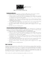
CONNECTING THE OUTPUTS
The Multi-Station Remote Alarm activates relay contacts in response to alarm conditions. These relay contacts
can be connected to any external device that is activated by the opening or closing of a switch. Examples would
be CONCOA’s telephone dialer, a Warning Light, an external buzzer, or another monitoring or alarm system.
Whatever the connecting device, care must be taken not exceed the rating of the relay contacts (Table 3). Refer
to Table 4 for the pin assignments for the Output Connector.
Notch