


-6-
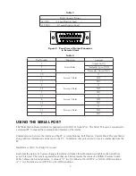
Using the pin assignments shown in Table 1 and the connector views in Figure 3 and Figure 4, solder the wires
to the appropriate pins. After soldering is complete attach the cable cover, cable retainer, and locking nut to the
circular connector plug. Also, attach the connector cover to the Input connector. Finally, insert the small screws
that came with the Input Connector kit into the holes on the ears of the Input Connector so that the heads of
the screws face the wire side of the connector. Slide the retainer clips on to the ears of the Input Connector to
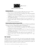
capture the screws. See Figure 5.
Plug the Input Connector side of the cable into the Remote Alarm and secure it by tightening the small screws.
Plug the circular connector into the Autoswitch securing it by turning the locking nut until it locks.
Figure 5
OPTION 2: For Autoswitch Systems that have a 4 pin circular connector.
If the Multi-Station Remote Alarm is being used to replace the previous multi-station Alarm (PN 5295298,
5295300) use the instructions that follow.
The existing Autoswitch system (522, 523, 536, and 537 prior to May 2002) came equipped with a 4 pin
circular connector. If it is already connected to an alarm, the 4 conductor cable already exists. Remove the
cable from the old alarm by unscrewing the wires from the terminal block. Cut the end of the cable so that
the wires that went into the terminals on the terminal block are removed. Remove the outer jacket of the
cable to expose approximately 1-1/2 inches of the internal conductors. Strip away 1⁄4 inch of the insulation
on each of the 4 conductors. Tin the leads of the conductors.
Using the pin assignments shown in Table 2 , and the connector views in Figure 6 and Figure 7, solder the
wires to the appropriate pins of the Input Connector. You will need to remove the protective cover, cable
retainer, and locking nut to the circular connector plug to see the pin outs. After soldering is complete re-
assemble the 4 pin plug assembly and attach the connector cover to the Input Connector. Finally, insert the
small screws that came with the Input Connector kit into the holes on the ears of the Input Connector so
that the heads of the screws face the wire side of the connector. Slide the retainer clips on to the ears of the
Input Connector to capture the screws.
Plug the Input Connector side of the cable into the Remote Alarm and secure it by tightening the small
screws. Plug the circular connector into the Autoswitch securing it by turning the locking nut until it locks.
You will need to change DIP switch 5 when using this Option.