Concoa 529 5310 Installation And Operation Instruction Manual Download Page 11

-11-

Disabling the Audible Alarm
The Multi-Station Remote Alarm is factory set to allow the audible alarm to sound.  To silence this alarm:

1.    Make sure AC power is OFF and unplug the Power cord from the Remote Alarm.
2.    It is best to set the unit on a flat surface.  With the Alarm placed so that the Input/Output connectors 

are facing towards you, unscrew the four (4) screws that hold the cover on.   They are retained in the 
cover so there is no need to remove them completely.

3.    Carefully lift the cover.  There are two cables that connect the cover to the base of the unit.  Without 

unplugging these cables, carefully set the cover back enough to gain access to the DIP switches located 
inside in the upper left hand corner

4.    Locate the DIP switches and then using a stylus or small screwdriver, close (turn on) the DIP switch for 

the Audible Alarm Silence (DIP switch 6).  Refer to Figure 8 to select the correct DIP switch.

5.    Place the cover back on the base.  Be careful not to pinch the cables coming from the cover.  Tighten 

the screws.

6.    Reconnect the power cord and plug unit in.

Selecting Normally Open or Normally closed pressure switches
The Multi-Station Remote Alarm can be configured to recognize either a normally open or a normally closed 
pressure switch.  The factory default is normally open.  This is defined as the state of the switch when the needle 
of the gauge is at 0 pressure.  To change this from normally open to normally closed:

1.  Make sure AC power is OFF and unplug the Power cord from the Remote Alarm.

2.    It is best to set the unit on a flat surface.  With the Alarm placed so that the Input/Output connectors 

are facing towards you, unscrew the four (4) screws that hold the cover on.   They are retained in the 
cover so there is no need to remove them completely.

3.    Carefully lift the cover.  There are two cables that connect the cover to the base of the unit.  Without 

unplugging these cables, carefully set the cover back enough to gain access to the DIP switches located 
inside in the upper left hand corner

4.    Locate the DIP switches and then using a stylus or small screwdriver, close (turn on) the DIP switch for 

the Pressure Switch Type (DIP switch 5).  Refer to Figure 8 to select the correct DIP switch.

5.    Place the cover back on the base.  Be careful not to pinch the cables coming from the cover.  Tighten 

the screws.

6.    Reconnect the power cord and plug unit in.

TEST MODE

The Multi-Station Remote Alarm has a Self-Test Mode.  In this mode the status indicator lights, Output Relays, 
audible alarm, and Serial Port are exercised.  The test sequence involves individually lighting each of the eight (8) 
status indicator lights, first in red then in green.  Each light stays lit for approximately 2 seconds.  This is followed 
by individually activating each of the five (5) Output Relays. The relays stay on for approximately 4 seconds.  After 
the relays have been activated, the audible alarm is turned ON.  Finally, the Serial Port sends out a code (02h, AAh, 
03h).  When the test sequence is complete the unit returns to normal operation.

This test mode can be a useful tool in determining where a problem exists in the system.

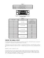
Figure 10 - Serial Connector Rear View
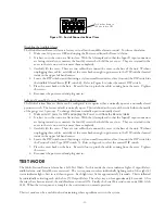
Push rocker down on

this side to turn ON

Summary of Contents for 529 5310

Page 1: ...talling or Operating Read and Comply with These Instructions Controls Corporation of America 1501 Harpers Road Virginia Beach VA 23454 To Order Call 1 800 225 0473 or 757 422 8330 Fax 757 422 3125 www...

Page 2: ...s that are brought to the Output Connector so they may be used to control an external device The status indicator lights are organized into pairs representing the Left Bank and Right Bank of an Autosw...

Page 3: ...mally closed switch One example of such a device would be the CONCOA telephone dialer PN 5295306 Connections to the Alarm are made through input and output connectors Customer supplied cables are easi...

Page 4: ...AUTOSWITCH To connect the Multi Station Remote Alarm to an Autoswitch system an interface cable must be made The Autoswitch systems are shipped with a connector that is used for this cable An Input C...

Page 5: ...status RIGHT BANK 5 2 alarm 4 15 RBSW status 3 3 12 6 16 Gnd 2 LEFT BANK 2 4 alarm 1 17 LBSW status RIGHT BANK 5 5 alarm 4 18 RBSW status 3 6 12 6 19 Gnd 3 LEFT BANK 2 7 alarm 1 20 LBSW status RIGHT B...

Page 6: ...rm the 4 conductor cable already exists Remove the cable from the old alarm by unscrewing the wires from the terminal block Cut the end of the cable so that the wires that went into the terminals on t...

Page 7: ...BANK 1 12 12 2 24 LBSW status RIGHT BANK 3 23 RBSW status 4 25 Gnd Table 2 CONNECTING THE OUTPUTS The Multi Station Remote Alarm activates relay contacts in response to alarm conditions These relay co...

Page 8: ...the Alarm will make this information available to the Serial Port as an 8 bit word The data is organized such that each bit represents the status of a BANK Pressure Switch Table 5 shows the bit assig...

Page 9: ...is limited to the following Command Code Keystroke Definition CAN Hex 18 Cntrl X Cancel ENQ Hex 05 Cntrl E Enquire STX Hex 02 Cntrl B Start of Text ETX Hex 03 Cntrl C End of Text DC4 Hex 14 Cntrl T D...

Page 10: ...o set the unit on a flat surface With the Alarm placed so that the Input Output connectors are facing towards you unscrew the four 4 screws that hold the cover on They are retained in the cover so the...

Page 11: ...m the Remote Alarm 2 It is best to set the unit on a flat surface With the Alarm placed so that the Input Output connectors are facing towards you unscrew the four 4 screws that hold the cover on They...

Page 12: ...ing Option 2 4 pin connector Autoswitch check that DIP switch 5 is properly set Refer to Configuring the Remote Alarm section of the manual Outputs do not appear to be functioning 1 Check the cable to...

Page 13: ...LECTRICAL SPECIFICATIONS Multi Station Remote Alarm 120 Volt Version 120 Volts 10 50 60 hz 6VA 220 Volt Version 220 Volts 10 50 60 hz 6VA Fuses 120 Volt Version 0 5A normal blow type 3AG 220 Volt Vers...

Page 14: ...14 THIS PAGE INTENTIONALLY LEFT BLANK...

Page 15: ...one other than CONTROLS CORPORATION OF AMERICA or if the equipment has been subject to abuse misuse negligence or accident CONTROLS CORPORATION OF AMERICA s sole and exclusive obligation and Buyer s s...

Page 16: ...Number Description 1 5295310 01 001 120 VAC MULTI STATION REMOTE ALARM 1 5295311 01 001 220 VAC MULTI STATION REMOTE ALARM INCLUDES 1 8308824 120 VAC MULTI STATION REMOTE ALARM 1 8308825 220 VAC MULTI...

Reviews: