RocketPort® 485 Hardware Installation
2 of 8
Before Installing the Hardware
Read this subsection:
•
If you already have one or more RocketPort ISA cards
installed in your system.
•
If you plan to install a combination of RocketPort ISA
and RocketPort PCI cards at this time.
Installing Both RocketPort ISA and PCI Cards:
You must complete installation of all RocketPort PCI cards
before beginning to install any RocketPort ISA cards.
Explanation:
I/O addressing for RocketPort PCI cards is handled
automatically by the computer’s BIOS when you first
power up the computer after installing the cards.
I/O addresses for RocketPort ISA cards are set manually
using DIP switches on the card. If you install an ISA card
before installing a RocketPort PCI card, the ISA card
addressing may interfere with the computer’s ability to
recognize the RocketPort PCI card which may prevent the
PCI card from functioning properly.
Additional Considerations:
If you are mixing RocketPort ISA and PCI cards, set the
DIP switches on the ISA cards so that the first ISA card
you install is the “first” card for I/O addressing purposes,
even if it is physically the second, third, or fourth card that
you install. See the Setting the DIP Switches discussion for
switch information.
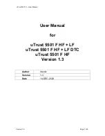
Supplying Power to External Devices
The power connector on the RocketPort 485 card is a
standard hard drive-type power connector. You can use
this connector to provide voltage to peripheral devices on
Ports 3 through 8.
To use the power option, connect the jumpers before
installing the card. See the Installing the RocketPort
Hardware discussion for configuring this feature.
Note: Ports 3 through 8 are equipped with fuses. If an
external device draws more than 0.5 amps, the fuse
for that port automatically breaks the circuit. The
fuse remains in the tripped condition until the short
or over current condition is corrected. At this time,
the fuse will reset and the circuit will be ready for
current to be applied again.
The pinout for this connector is shown below:
Note: Power can be supplied only through DB9 or DB25
connectors. It cannot be supplied through RJ45
connectors.
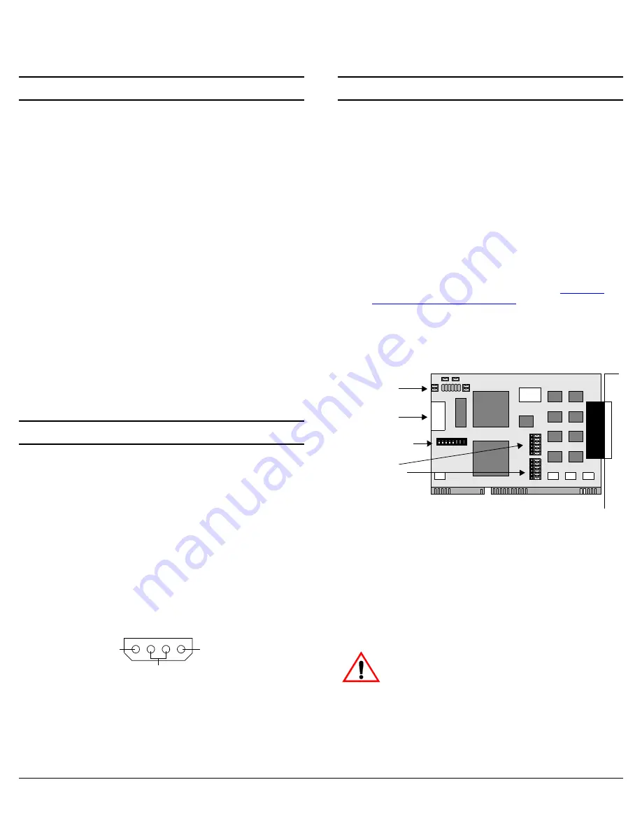
Installing the RocketPort Hardware
Hardware installation consists of:
•
Configuring I/O addresses
•
Configuring RS-485 mode usage on Ports 1 and 2
•
Installing the card in the system
•
Connecting the peripherals
Note: After installing the hardware, you must install the
device driver for your operating system.
Use the following procedure to install the card.
1.
If required, change the DIP switches (default is 180
hexadecimal) on the card to the desired settings. See
the Setting the DIP Switches discussion towards the
end of this Hardware Installation document.
Note: If you are installing PCI and ISA RocketPort cards,
install the PCI cards and driver before installing
and configuring the ISA cards. See the
installation and configuration
driver
readme
file for information.
2.
To use RS-485 on Ports 1 and 2, move all six pins on
the port you want to use RS-485 to the left and center
position. (When all six pins are in the center and right
positions, the port is configured for RS-232.)
Note: In addition, you must configure the ports for RS-485
operation during the driver installation. For more
information, see the Software Installation and
Configuration documentation or the
readme
file with
the driver.
3.
To use the Power feature for Ports 3 through 8, connect
the jumper for each port.
When using this card with interfaces other than
the DB9 box, do not use the Power feature. Using
this feature with Quad/Octacable interfaces
may produce unacceptable voltage loss under
load.
4.
Turn off your computer.
5.
Remove the system cover.
6.
Select an ISA or EISA expansion slot.
NC
GND
+5V
1 2 3 4
Jumpers*
Ports 3 - 8
Power
Connector
DIP Switches
Port 1**
Port 2**
Jumpers
* The Power feature is disabled as the factory default
(jumpers NOT connected).
** Port 1 is labeled Port 0 on the card and Port 2 is
labeled Port 1 on the card. Ports 1 and 2 are set to
RS-232 as the factory default.
Caution