background image


75

9.5.3 Passwords 

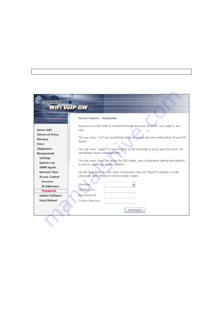
The Passwords option configures the user account access passwords for the 

device.  Access to the device is limited to the following three user accounts:  


root 

is to be used for local unrestricted access control. 


support 

is to be used


for


remote maintenance of the device 


user 

is to be used


to view information and update device firmware. 


NOTE:


Default account passwords can be found in section 3.1 Default Settings 

 
Use the fields in the screen below to select a username and change its password.  

Passwords must be 16 characters or less.  Click 

Save/Apply

 to continue. 


Summary of Contents for CT-820C

Page 1: ...CT 820C VoIP Gateway User s Manual Version A2 0 December 26 2007 261053 034 ...

Page 2: ...e manual revision or software upgrades visit Comtrend Corporation at http www comtrend com Warning Before servicing disconnect power and telephone lines from the device Use an appropriate power supply and a UL Listed telephone line cord Power specifications are clearly stated in Appendix C Specifications Copyright Copyright 2007 Comtrend Corporation All rights reserved The information contained he...

Page 3: ...ual Servers 29 5 3 2 Port Triggering 31 5 3 3 DMZ Host 33 5 4 SECURITY 34 5 4 1 IP Filtering 34 5 4 2 Parental Control 37 5 5 QUALITY OF SERVICE 38 5 6 ROUTING 39 5 6 1 Default Gateway 39 5 6 2 Static Route 40 CHAPTER 6 WIRELESS 41 6 1 BASIC 41 6 2 SECURITY 43 6 3 MAC FILTER 46 6 4 WIRELESS BRIDGE 48 6 5 ADVANCED 49 6 6 STATION INFO 52 CHAPTER 7 VOICE 53 7 1 SIP 53 7 2 DIAL PLAN 58 7 3 TELEPHONE C...

Page 4: ...3 9 5 2 IP Addresses 74 9 5 3 Passwords 75 9 6 UPDATE SOFTWARE 76 9 7 SAVE AND REBOOT 77 APPENDIX A FIREWALL 78 APPENDIX B PIN ASSIGNMENTS 81 APPENDIX C SPECIFICATIONS 82 APPENDIX D SSH CLIENT 84 ...

Page 5: ...ovides VoIP via standard analog phones 1 1 Features VoIP and router integrated 802 11g b access point VPN passthrough QoS for voice DNS SRV Dial plan Call hold Call waiting Call transfer Call forwarding 3 way conference Direct number dialing Supports emergency call Day time parental control T 38 fax relay and passthrough Caller ID presentation and restriction Supports life line PSTN alive when pow...

Page 6: ...5 1 2 Application The following diagram depicts the application of the CT 820C ...

Page 7: ...The FXS phone 1 is off hook PHONE1 Off The FXS phone 1 is on hook Green On The FXS phone 2 is off hook PHONE2 Off The FXS phone 2 is on hook Green On The wireless module is ready and idle Off The wireless module is disabled WLAN Green Blink Data transmitting or receiving over WLAN Green On An FXO line is off hook LINE Off An FXO line is on hook Green On An Ethernet Link is established WAN Off An E...

Page 8: ...nection to Phone1 Phone2 Connect a telephone to either RJ11 port for VoIP service Reset Button Restore the default parameters of the device by holding down the Reset button until the front panel LED indicators start blinking simultaneously 5 seconds If held down for more than 12 seconds the device will go into a firmware update state CFE boot mode The user can then update the device from any web b...

Page 9: ... WAN IP address none Technical Note During power on the device initializes all settings to default values It will then read the configuration profile from the permanent storage section of flash memory The default attributes are overwritten when identical attributes with different values are configured The configuration profile in permanent storage can be created via the web user interface or telne...

Page 10: ...atically in the dialog box shown below STATIC IP Mode To configure the device manually your PC must have a static IP address within the 192 168 1 x subnet Follow the steps below to configure your PC IP address to use subnet 192 168 1 x The following assumes you are running Windows XP STEP 1 From the Network Connections window open the Local Area Connection You may also access this screen by double...

Page 11: ... login to the web user interface NOTE The default settings for this device can be found in 3 1 Default Settings STEP 1 Start the Internet browser and enter the default IP address for the device in the Web address field For example if the IP address is 192 168 1 1 type http 192 168 1 1 NOTE For local administration i e LAN access the PC running the browser must be attached to the Ethernet and not n...

Page 12: ...11 ...

Page 13: ...he one below Enter the default username and password as defined in section 3 1 Default Settings Click OK to continue NOTE The login password can be changed later see 9 5 3 Passwords STEP 3 After successfully logging in you will reach this screen ...

Page 14: ...n the Advanced Setup menu if NAT and Firewall are enabled the main menu will display the NAT and Security submenus If either is disabled their corresponding menu will also be disabled Device Info is the first selection on the main menu so it will be discussed first Subsequent chapters will introduce the other main menu options in sequence The Device Info submenu outlined in red in the screenshot b...

Page 15: ...ory Shows the ATM service classes Service Shows the name for WAN connection Interface Shows connection interfaces Protocol Shows the connection type such as PPPoE PPPoA etc Igmp Shows the status of the IGMP Proxy function State Shows the connection state of the WAN connection Status Lists the WAN or PVC status ex Up Down or Authentication Failure IP Address Shows IP address for WAN interface ...

Page 16: ...net and Wireless interfaces on the LAN Interface Shows connection interfaces in the following format nas_ VPI number_VCI number These interfaces are devised by the system and not the user Received Transmitted Bytes Pkts Errs Drops Rx TX receive transmit packet in Byte Rx TX receive transmit packets Rx TX receive transmit the packets which are errors Rx TX receive transmit the packets which are dro...

Page 17: ... as PPPoE PPPoA etc Interface Shows connection interfaces in the following format nas_ VPI number_VCI number These interfaces are devised by the system and not the user Received Transmitted Bytes Pkts Errs Drops Rx TX receive transmit packet in Byte Rx TX receive transmit packets Rx TX receive transmit the packets which are errors Rx TX receive transmit the packets which are dropped ...

Page 18: ... Destination Flag U route is up reject route G use gateway H target is a host R reinstate route for dynamic routing D dynamically installed by daemon or redirect M modified from routing daemon or redirect Metric The distance to the target usually counted in hops It is not used by recent kernels but may be needed by routing daemons Service Shows the name for WAN connection Interface Shows connectio...

Page 19: ...18 4 4 ARP Click ARP to display the ARP information ...

Page 20: ...19 4 5 DHCP Click DHCP to display the DHCP Leases information ...

Page 21: ...o configure WAN interfaces The screen below shows all configured WAN connections The table below gives more details STEP 1 Click the Edit button next to the WAN connection you wish to configure Con ID ID for WAN connection Category ATM service category e g UBR CBR Service Name of the WAN connection Interface Name of the interface for WAN Protocol Shows IPoW or PPPoE modes Igmp Shows enable or disa...

Page 22: ...ion screen will display as below Quality of Service QoS is enabled when the box at bottom is checked Click Next STEP 3 On this screen you can choose either PPPoE or IPoE connection types Once you have chosen click Next to proceed ...

Page 23: ...rticular requirements of the service provider A maximum of 256 characters is allowed for the PPP user name and a maximum of 32 characters for PPP password PPPoE service name For PPPoE service PADI requests contain a service name tag Some PPPoE servers or BRAS of ISP check this service name tag for connection Dial on Demand The device can be configured to disconnect if there is no activity for a pe...

Page 24: ...ult gateway and DNS server to the PC through DHCP using the LAN interface IP address The device extends the IP subnet at the remote service provider to the LAN PC That is the PC becomes a host belonging to the same IP subnet The device bridges the IP packets between WAN and LAN ports unless the packet is addressed to the device s LAN IP address Use Static IP Address Unless your service provider sp...

Page 25: ...rotocol is a protocol used by IP hosts to report their multicast group memberships to any immediately neighboring multicast device s STEP 6 Click Next to display the WAN Setup Summary screen that presents the entire configuration summary review Click Back to modify the settings Click Save Reboot and skip to Step 10 ...

Page 26: ...by your ISP to configure the WAN IP settings DHCP mode must be enabled when Obtain an IP address automatically is chosen Changing the default gateway or the DNS affects the whole system Where Static mode is selected the IP address and subnet mask must be entered however the Use WAN interface field does not need to be selected STEP 8 The next screen combines NAT IGMP and WAN service selection optio...

Page 27: ...ox to enable IGMP multicast proxy IGMP Internet Group Membership Protocol is a protocol used by IP hosts to report their multicast group memberships to any immediately neighboring multicast device s STEP 9 Click Next to display the WAN Setup Summary screen that presents the entire configuration summary review Click Back to modify the settings STEP 10 At this point the device will save the configur...

Page 28: ...e LAN port Subnet Mask Enter the subnet mask for the LAN port Enable UPnP Tick the box to enable Enable IGMP Snooping Enable by ticking the box Standard Mode In standard mode multicast traffic will flood to all bridge ports when no client subscribes to a multicast group even if IGMP snooping is enabled Blocking Mode In blocking mode the multicast data traffic will be blocked and not flood to all b...

Page 29: ...up 5 3 1 Virtual Servers Virtual Servers allow you to direct incoming traffic from the WAN side identified by Protocol and External port to the Internal server with private IP addresses on the LAN side The Internal port is required only if the external port needs to be converted to a different port number used by the server on the LAN side A maximum of 32 entries can be configured To add a Virtual...

Page 30: ...figured External Port End Enter the ending external port number when you select Custom Server When a service is selected the port ranges are automatically configured Protocol User can select from TCP TCP UDP or UDP Internal Port Start Enter the internal port starting number when you select Custom Server When a service is selected the port ranges are automatically configured Internal Port End Enter...

Page 31: ...ts in the firewall when an application on the LAN initiates a TCP UDP connection to a remote party using the Triggering Ports The device allows the remote party from the WAN side to establish new connections back to the application on the LAN side using the Open Ports A maximum of 32 entries can be configured To add a Trigger Port click the Add button The following screen will display ...

Page 32: ...t number when you select custom application When an application is selected the port ranges are automatically configured Trigger Protocol User can select from TCP TCP UDP or UDP Open Port Start Enter the starting open port number when you select custom application When an application is selected the port ranges are automatically configured Open Port End Enter the ending open port number when you s...

Page 33: ...he WAN that do not belong to any of the applications configured in the Virtual Servers table to the DMZ host computer Enter the computer s IP address and click Apply to activate the DMZ host Clear the IP address field and click Apply to deactivate the DMZ host ...

Page 34: ...ffic by specifying a new filter name and at least one condition below All of the specified conditions in this filter rule must be satisfied for the rule to take effect Click Save Apply to save and activate the filter Outgoing IP Filter NOTE The default setting for all Outgoing traffic is ACCEPTED To add a filtering rule click the Add button The following screen will display ...

Page 35: ...e IP address Source Subnet Mask Enter source subnet mask Source Port port or port port Enter source port number or port range Destination IP address Enter destination IP address Destination Subnet Mask Enter destination subnet mask Destination port port or port port Enter destination port number or port range ...

Page 36: ...NOTE The default setting for all Incoming traffic is BLOCKED To add a filtering rule click the Add button The following screen will display To configure the parameters please reference the Outgoing IP Filter table ...

Page 37: ...his feature restricts access of a selected LAN device to an outside network through the router as per chosen days of the week and the chosen times Click Add to display the following screen See below for instructions Click Save Apply to apply the settings ...

Page 38: ...AN device is entered Days of the Week Days of the week when the restrictions are applied Start Blocking Time The time when restrictions on the LAN device are put into effect End Blocking Time The time when restrictions on the LAN device are lifted 5 5 Quality of Service Choose the broadband network environment Cable or ADSL Then set the maximum upstream bandwidth rate in Kbps Click Save or Save Re...

Page 39: ... is selected this device will accept the first received default gateway assignment from one of the enabled PVC s If the checkbox is not selected enter the static default gateway and or WAN interface Click Save Apply button to save it NOTE After enabling the Automatic Assigned Default Gateway the device must be rebooted to activate the assigned default gateway ...

Page 40: ...atic routes Choose Add or Remove to configure the static routes Click the Add button and the following screen will display Enter the destination network address subnet mask gateway AND OR available WAN interface then click Save Apply to add the entry to the routing table ...

Page 41: ...access point set the wireless network name and restrict the channel set 6 1 Basic This screen allows you to enable or disable the wireless LAN interface hide the network from active scans set the wireless network name also known as SSID and restrict the channel set based on country requirements ...

Page 42: ...e access points You can also use other software programs such as NetStumbler to view available access points SSID Sets the wireless network name SSID stands for Service Set Identifier All stations must be configured with the correct SSID to access the WLAN If the SSID does not match that user will not be granted access The naming conventions are Minimum is one character and maximum number of chara...

Page 43: ...on can request authentication The system that needs to authenticate with another wireless station sends an authentication management frame that contains the identity of the sending station The receiving station then sends back a frame that indicates whether it recognizes the identity of the sending station Under shared key authentication each wireless station is assumed to have received a secret s...

Page 44: ...vided Open system authentication only performs identity verifications Different authentication type pops up different settings requests Choosing 802 1X enter RADIUS Server IP address RADIUS Port RADIUS key and Current Network Key Also enable WEP Encryption and select Encryption Strength Select the Current Network Key and enter 13 ASCII characters or 26 hexadecimal digits for 128 bit encryption key...

Page 45: ...er of binary bits comprising the session key file This means that session keys with a greater number of bits have a greater degree of security and are considerably more difficult to forcibly decode This drop down menu sets either a 64 8 bit 5 character or 10 character hexadecimal or 128 8 bit 13 character or 10 character key If you set a minimum 128 bit key strength users attempting to establish a...

Page 46: ...resses that may connect to the access point and thus dictate what devices are authorized to access the wireless network When a device is using MAC filtering any address not explicitly defined will be denied access MAC Restrict mode Off disables MAC filtering Allow permits access for the specified MAC address deny reject access of the specified MAC address then click the SET button To delete an ent...

Page 47: ...s point Deny Prevents PCs with listed MAC from connecting to the access point MAC Address Lists the MAC addresses subject to the Off Allow or Deny instruction The Add button prompts an entry field that requires you type in a MAC address in a two character 6 byte convention xx xx xx xx xx xx where xx are hexadecimal numbers The maximum number of MAC addresses that can be added is 60 ...

Page 48: ...onality Wireless bridge functionality will still be available and wireless stations will be able to associate to the AP Select Disabled in Bridge Restrict to disable wireless bridge restriction Any wireless bridge will then be granted access Selecting Enabled or Enabled Scan enables wireless bridge restriction Only those bridges selected in Remote Bridges will be granted access Mode Options AP Mod...

Page 49: ...solation Select On or Off By enabling this feature wireless clients associated with the Access Point will be able to connect to each other Band The new amendment allows IEEE 802 11g units to fall back to speeds of 11 Mbps so IEEE 802 11b and IEEE 802 11g devices can coexist in the same network The two standards apply to the 2 4 GHz frequency band IEEE 802 11g creates data rate parity at 2 4 GHz wi...

Page 50: ... Card invokes its RTS CTS mechanism Packets that exceed the specified RTS threshold trigger the RTS CTS mechanism The NIC transmits smaller packet without using RTS CTS The default setting of 2347 maximum length disables RTS Threshold DTIM Interval Delivery Traffic Indication Message DTIM also known as Beacon Rate The entry range is a value between 1 and 65535 A DTIM is a countdown informing clien...

Page 51: ...de to 54g LRS if you are experiencing difficulty with legacy 802 11b equipment 54g Protection In Auto mode the device will use RTS CTS to improve 802 11g performance in mixed 802 11g 802 11b networks Turn protection off to maximize 802 11g throughput under most conditions Preamble Type Short preamble is intended for application where maximum throughput is desired but it doesn t cooperate with the ...

Page 52: ... BSSID is the MAC Medium Access Control address of the AP Access Point and in Independent BSS or ad hoc networks the BSSID is generated randomly Associated Lists all the stations that are associated with the Access Point along with the amount of time since packets were transferred to and from each station If a station is idle for too long it is removed from this list Authorized Lists those devices...

Page 53: ... multimedia conferencing over IP It is designed to address the functions of signaling and session management within a packet telephony network Signaling allows call information to be carried across network boundaries Session management provides the ability to control the attributes of an end to end call Session Initiation Protocol is a peer to peer protocol There are four components in the SIP sta...

Page 54: ...54 To access the SIP configuration screen click SIP from the Voice submenu Once the settings are configured click Apply and Save All VoIP Parameters to reset the VoIP service to use the new settings ...

Page 55: ... VoIP provider Enable SIP tag matching Uncheck for Vonage Interop Select if required by your VoIP provider Remote server for SIP log messages Enable or disable remote server SIP log messages DispName The caller ID display name VoIP Phone Number As the modem has two FXS two phone numbers can be listed Auth ID The authentication username for the Registrar Proxy as assigned by the VOIP service provid...

Page 56: ...e When you take your VoIP phone off hook you can set the tone sound you hear to let you know you have selected a VoIP line It is advised to have different sounding tone with the normal PSTN tone as you then know your VoIP account is active and connected and you will not make expensive calls on your normal PSTN account if your VoIP account is inactive for whatever reason Enable Trusted IP for SIP s...

Page 57: ...will be displayed When disabled mark the priority and type of IP service for all SIP upstream traffic Assign Differentiated Services Code Point DSCP Mark The selected Code Point gives the corresponding priority to the packets that satisfies the rules set below Media Qos The function set creates a traffic class rule to classify the VoIP RTP upstream traffic assign queuing priority and optionally ov...

Page 58: ...er customization All three screens are similar in design as can be seen in the figures below Outgoing Incoming Advance Each screen has the same four buttons at top Add Click this button to go to the add rule screen Follow the detailed instructions given there After completing the form click Apply to add a new dial plan rule Remove Select the dial plan rule you wish to delete and click the Remove b...

Page 59: ...n option for our example To begin select Advanced from the Dial Plan menu The user interface should display as below Click the Add button to go to the Advance rule add screen shown below Index Use this radio button to select a rule for modification or removal Priority All the rules will be applied in order according to their priority This field can be set to any number between 0 and 32767 with low...

Page 60: ...lue to accept all 11 digits of the dial sequence Step 5 In the DeleteDigit field enter 3 to delete the 123 prefix Step 6 Enter 002 in the InsertDigit field to add 002 as the prefix Step 7 Click the Apply button to return to the Advance configuration screen Step 8 Click Apply Save to apply this rule to all outgoing calls NOTE This prefix swap example is especially helpful for corporate environments...

Page 61: ...line at address 10 136 64 23 All devices have to be on the same Class C subnet 24 bit subnet mask To dial an IP address directly dial the IP address digits using keypad as the dot Complete the address with a final or When using IP address dialing it is not possible to specify which line at a gateway is called so the gateway always routes IP address dialed calls to the first line Network busy tone ...

Page 62: ... dial 61 Call forward feature settings Busy or All takes priority over the call waiting feature The call waiting feature is ignored on new incoming calls if there is already a call on hold or in conference Call Forward Number To set the call forward number dial 74 then the number Note that this does not actually enable forwarding to do so select the call forward action as described below To disabl...

Page 63: ...tes that the WAN interface from the modem ADSL cable is connected to the WAN port of this device Fail Indicates that the device does not detect the WAN interface from the modem ADSL cable Wireless connection Pass Indicates that the Wireless interface from your computer is connected to the wireless network Down Indicates that the device does not detect the wireless network Ping Default Gateway Pass...

Page 64: ...the primary Domain Name Server DNS Fail Indicates that the device was unable to communicate with the primary Domain Name Server DNS It may not have an effect on your Internet connectivity Therefore if this test fails but you are still able to access the Internet there is no need to troubleshoot this issue ...

Page 65: ...screen allows for the backup retrieval and restoration of settings Each of these functions is accessed from the Settings submenu and described in more detail in the following discussion 9 1 1 Backup Settings Select Backup from the Settings submenu to access the screen shown below Click the Backup Settings button to save the current configuration settings You will be prompted to define the location...

Page 66: ...bmenu to access the screen shown below Enter a previously saved configuration backup file in the Settings File Name field and click the Update Settings button to load it If you forget the filename and path you can search your PC by clicking on the Browse button ...

Page 67: ...ration window and wait for 2 minutes before reopening your web browser If necessary reconfigure your PC s IP address to match your new configuration After a successful reboot the browser will return to the Device Info screen If the browser does not refresh to the default page close and restart the browser NOTE The Restore Default function has the same effect as the reset button The device board ha...

Page 68: ...m events and configuration of related options The default setting for the System Log is enabled Follow the steps below to enable and view the System Log STEP 1 Click Configure System Log to continue Step 2 Select from the desired system log options see table below and then click Save Apply ...

Page 69: ...g level is Debugging which is the lowest critical level The following log levels are Emergency is the most serious event level whereas Debugging is the least important For instance if the log level is set to Debugging all the events from the lowest Debugging level to the most critical level Emergency level will be recorded If the log level is set to Error only Error and the level above will be log...

Page 70: ...ver or both simultaneously If remote mode is selected view system log will not be able to display events saved in the remote syslog server When either Remote mode or Both mode is configured the WEB UI will prompt the user to enter the Server IP address and Server UDP port 3 Click View System Log The results are displayed in as follows ...

Page 71: ... Simple Network Management Protocol SNMP allows a management application to retrieve statistics and status from the SNMP agent in this device Select the desired values and click Save Apply to configure the SNMP options ...

Page 72: ... device To automatically synchronize with Internet timeservers tick the corresponding box displayed on this screen then click Save Apply On the screen below choose your Time Zone and click Save Apply to continue Field Descriptions First NTP time server Select your required server Second NTP time server Select second time server if required Time zone offset Select your local time zone ...

Page 73: ...P Addresses and Passwords Use Access Control to control local and remote management settings for the device 9 5 1 Services The Services option limits or opens the access services over the LAN or WAN These access services are available FTP HTTP ICMP SSH TELNET and TFTP Enable a service by ticking its checkbox Click Save Apply to continue ...

Page 74: ...he Access Control Mode is enabled only the IP addresses listed here can access the device Before enabling Access Control Mode add IP addresses with the Add button On this screen enter the IP address of a local PC which you wish to give management permissions Click Save Apply to continue ...

Page 75: ... for local unrestricted access control support is to be used for remote maintenance of the device user is to be used to view information and update device firmware NOTE Default account passwords can be found in section 3 1 Default Settings Use the fields in the screen below to select a username and change its password Passwords must be 16 characters or less Click Save Apply to continue ...

Page 76: ... Name field or click the Browse button to locate the image file Step 3 Click the Update Software button once to upload and install the file NOTE 1 The update process will take about 2 minutes to complete The device will reboot and the browser window will refresh to the default screen upon successful installation It is recommended that you compare the Software Version at the top of the Device Info ...

Page 77: ...ay be necessary to reconfigure your TCP IP settings to adjust for the new configuration For example if you disable the DHCP server you will need to apply Static IP settings In this case see section 3 2 TCP IP Settings for detailed instructions NOTE If you lose all access to the web user interface simply press the reset button on the rear panel for 5 7 seconds to restore to default settings ...

Page 78: ... Enabled all IP traffic from LAN is allowed By setting up one or more filters particular packet types coming from the LAN can be dropped Filter Name User defined Filter Name Protocol Can take on any values from TCP UDP TCP UDP or ICMP Source IP Address Source Subnet Mask Packets with the particular Source IP Address Source Subnet Mask combination will be dropped Source Port This can take on either...

Page 79: ... can be Accepted Filter Name User defined Filter Name Protocol Can take on any values from TCP UDP TCP UDP or ICMP Source IP Address Source Subnet Mask Packets with the particular Source IP Address Source Subnet Mask combination will be accepted Source Port This can take on either a single port number or a range of port numbers Packets having a source port equal to this value or falling within the...

Page 80: ...cts access of a selected LAN device to an outside Network through the router as per chosen days of the week and the chosen times User Name Name of the Filter Browser s MAC Address Displays MAC address of the LAN device on which the browser is running Other MAC Address If restrictions are to be applied to a device other than the one on which the browser is running the MAC address of that LAN device...

Page 81: ...f the RJ11 Port Line port RJ11 Pin Definition Pin Definition 1 4 ADSL_TIP 2 5 3 ADSL_RING 6 Pin assignments of the LAN Port LAN Port RJ45 Pin Definition Pin Definition 1 Transmit data 5 NC 2 Transmit data 6 Receive data 3 Receive data 7 NC 4 NC 8 NC ...

Page 82: ... can be selected according to the environment Analog Interface FXS x 2 FXO x 1 Life Line WAN Connection PPPoE RFC 2516 DHCP Client Static IP Management SNMP SNTP Telnet Web based management Configuration backup and restoration Software upgrade via HTTP TFTP client and server or FTP server Centralized configuration and firmware upgrade via APS optional Bridge Functions Transparent bridging and lear...

Page 83: ...1a u G 729 ILBC RTP RFC 1889 SDP RFC 2327 Caller ID ETSI based Life line Emergency call Yes Echo cancellation G 168 Silence suppression Yes T 38 Fax passthrough Yes DTMF RFC2833 in band QoS Yes ToS DSCP bit tagging Yes Dial Plan Yes Power External power adapter Input AC100 240V Output DC12V 1 5A Environmental Conditions Operating temperature 0 50 degrees Celsius Relative humidity 5 90 non condensi...

Page 84: ...AN Use the device WEB UI to enable SSH access from LAN default is enabled type ssh l root 192 168 1 1 From WAN In the device use WEB UI to enable SSH access from WAN type ssh l support device WAN ip address To access the device using the Windows putty ssh client From LAN Use the device WEB UI to enable SSH access from LAN default is enabled type putty ssh l admin 192 168 1 1 From WAN In the device...

Reviews: