CommScope SYSTIMAX imVision  X User Manual Download Page 9

www.commscope.com 


User Guide 860633028 

June 2018 


Page 9 of 30 

© 2018 CommScope, Inc. All Rights Reserved 

Attention tone 

1 long, low tone 

Technician is requested to confirm an action. 
Error occurred. 
Diagnostic tests detected a problem. 


Following Prompts in the imVision System 


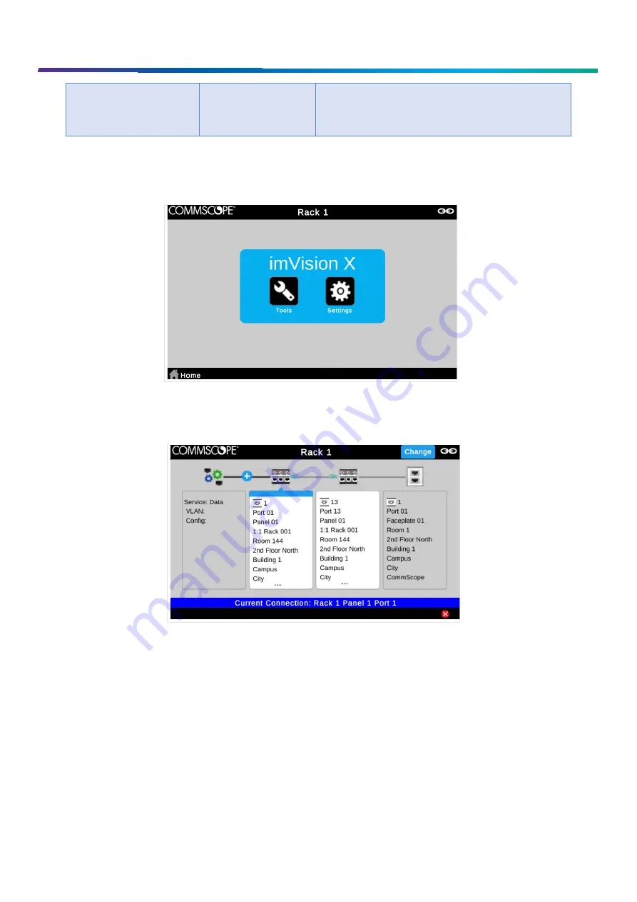
imVision Controller X Touchscreen Display 

The imVision system provides helpful feedback on its imVision Controller X display. While performing work on panels or 
responding to alarms, be sure to follow any prompts that appear on the display. 


Tracing Example on imVision Touchscreen Display 

Connecting imVision Controller X’s in a Zone 

zone

 or 

patching zone

 is a group of managed racks and cabinets (including mainframes) among which iPatch patch 

connections can be made. A managed rack is a rack that is managed by an imVision Controller or imVision Controller X. 
Although imVision Controllers and imVision Controller X’s are supported in the same zone, some functions (such as multi-
rack management from a single imVision Controller X) may be limited or disabled in such mixed zones. Additionally, an 
imVision Controller X must be installed in the first position in such a mixed zone. 
imVision Controller X’s do NOT support zones that also contain an iPatch Panel Manager or iPatch Rack Manager Plus. 
  

Summary of Contents for SYSTIMAX imVision X

Page 1: ...ION CONTROLLER X S IN A ZONE 9 ORDERING PANELS IN THE IMVISION SYSTEM 11 DELETING PANELS AND RACKS 11 NETWORK CONFIGURATION 11 NETWORK PORT USAGE 12 WEB USER INTERFACE 13 USERNAME AND PASSWORD FOR THE WEB USER INTERFACE 14 SCREEN LOCK PIN FEATURE 14 PATCHING MODE 15 PATCHING AND TRACING 16 PERFORMING GUIDED PATCHING JOBS 16 PERFORMING UNGUIDED PATCHING JOBS 16 TRACING A PATCH CONNECTION 16 CORRECT...

Page 2: ...Inc All Rights Reserved FIRMWARE UPDATE 23 REBOOTING THE UNIT AND RESETTING TO FACTORY DEFAULTS 24 CLEAR MEMORY 24 RESET BUTTON 24 Rebooting Using the RESET Button 25 Resetting to Factory Defaults Using the RESET Button 25 TROUBLESHOOTING 26 TRADE MARKS 30 CONTACT INFORMATION 30 ...

Page 3: ...k of electric shock Do not place this product on an unstable cart stand or table The product may fall causing serious damage to the product When installing imVision or iPatch equipment not described in this guide follow the instructions provided with that equipment Take care not to compromise the stability of the rack by installation of equipment The touchscreen display is designed to be used with...

Page 4: ...Vision Controller X logically infers when patch connections are added moved or deleted and updates the database accordingly In most configurations multiple imVision Controller X units are grouped and connected into patching zones Each patching zone requires a LAN connection in order to communicate with the System Manager server Each imVision Controller X has a touchscreen display that lets you int...

Page 5: ...D bar to the right of the screen on the imVision Controller X display will light up when attention is required Examples of cases when attention is required include pending jobs error and status alarms or unknown port connections that need confirmation Ready Screen When the imVision Controller X display first boots or is awakened after a sleep timeout a Ready screen is shown Pressing the Home butto...

Page 6: ...s options for configuring the imVision Controller X Options on the Settings menu include Network Settings Patching Mode Screen Lock Settings and Language Settings Information about Network Settings Patching Mode and Screen Lock Settings can be found in other sections of this User Guide Tools Menu The Tools menu contains options for obtaining information and for performing diagnostic and recovery t...

Page 7: ...on indicates the percentage of its power budget allocated to the current panels In multi rack configurations Panel Information indicates how many rack units of iPatch connectivity are available on each rack Test Panels This tool is used to obtain detailed debugging information for a panel and panel port This option can also be used to reconfigure module orientation for fiber modules Test Network T...

Page 8: ...Manager A job is a work order step involving the addition or removal or a connection to an iPatch port The number within the green circle indicates the total number of jobs for the zone The Alarms button appears when one or more alarms are present in the imVision Controller X Alarms may indicate configuration actions that are required to use the system or they may indicate hardware or firmware err...

Page 9: ...Vision Touchscreen Display Connecting imVision Controller X s in a Zone A zone or patching zone is a group of managed racks and cabinets including mainframes among which iPatch patch connections can be made A managed rack is a rack that is managed by an imVision Controller or imVision Controller X Although imVision Controllers and imVision Controller X s are supported in the same zone some functio...

Page 10: ... zone must be connected to each other in a chain using patch cords between the controllers In a zone the B or OUT port of one controller must connect to the A or IN port of the next controller If imVision Controllers are present in the zone ensure each imVision Controller s pushbutton switches are configured according the installation instructions for the imVision Controller Configure a Zone Conta...

Page 11: ...els from an ordered rack the system may prompt you to re order the panels Proceed with panel ordering as instructed above Deleting Panels and Racks The ImVision Controller X remembers each panel and each rack that it has communicated with in the past and will raise an alarm if communication with any of these items fails If a rack or panel is legitimately removed the user must view the associated a...

Page 12: ...anager 11 Verify System Manager trace details connectivity by pressing a port button and ensuring that the information shown in the circuit trace includes Room and Site information from System Manager Network Port Usage When connecting to the imVision Controller X through a hardware firewall or from a computer that has a software firewall it is important to ensure that appropriate communications p...

Page 13: ...r UDP 8515 System Manager Application Server imVision Controller X Trace detail responses sent from System Manager to imVision Controller X s Web User Interface The imVision Controller X includes a web user interface that is accessible by connecting a web browser to the imVision Controller X that is configured as a Network Manager Refer to the version specific release notes for a list of supported...

Page 14: ...oller and imVision Controller X firmware for the zone The default password should be changed using the web user interface Choose Change Password from the Passwords tab to get to a page that allows the password to be changed Web User Interface Home Screen and Location of Change Password Option Screen Lock PIN Feature When enabled the Screen Lock PIN feature locks an imVision Controller X display un...

Page 15: ...mal Local and Equipment The patching mode at the rack is set to Normal by default The patching mode can be changed temporarily at the imVision Controller X but the mode set in System Manager software will override a locally set mode during synchronization When the patching mode is set to something other than Normal the imVision Controller X shows the patching mode on the Ready screen below the Rac...

Page 16: ...ent the display and the correct LED on the panel will indicate where to add remove the patch on the iPatch Panel The display will also identify the non iPatch equipment When working with equipment connections be sure to press and hold the button above the corresponding iPatch port on the iPatch Panel for 2 seconds This will confirm that the job has been completed Completing this activity automatic...

Page 17: ...t trace The first step in correcting a patching error is to show a circuit trace for a targeted port To show a circuit trace press the panel button corresponding to an iPatch Panel port The LEDs associated with connected iPatch Panel ports will turn on On the display a graphical circuit trace will be shown along with a Change button Step 2 Use the Change button to break existing connection relatio...

Page 18: ... confirm a connection tap the Confirm tab on the display You will see a list of any patch connections that need to be confirmed On the display select the patch connection you want to confirm Then either Press and hold the port button on the iPatch panel that corresponds to the port where the other end of the cord is inserted and confirm on the display that the connection is complete or If the othe...

Page 19: ...e trace button above that port 4 If the port where the cord terminates is a fiber port both strands of the port are populated and the patch being confirmed is a simplex connection the system will ask which of the two strands is the strand being selected Use the A B toggle button to choose whether the B or A strand is the far end of the patch being confirmed When the correct connection is displayed...

Page 20: ...sion Controller X should point toward the dependent racks to which each connector is connected Ordering Dependent Racks When the system first detects an extender panel bus cable plugged into a or connector on the rear of the imVision Controller X base a screen will appear to identify the numeric order of the racks managed by the imVision Controller X Press Change Rack Order to toggle whether the h...

Page 21: ...ch Rack in Multi Rack Mode In multi rack mode the Panel Information option from the Tools menu shows a tabbed screen Each tab shows information about the panels shelves for a rack that is managed by the imVision Controller X The top line in the tabbed area shows the number of iPatch Rack Units that can be added in that rack in rack units RU A rack with no panels shelves starts with an available li...

Page 22: ...in other screens as well shows on which side of the Controller X s rack each dependent rack is located If a rack number or rack name is pressed the imVision Controller X will display rack information for that rack Tabbed Screens Some screens will have a tabbed interface to indicate separation of information according to each rack managed by the imVision Controller X Select the tab of the rack you ...

Page 23: ...ore downgrading firmware How to Update Firmware Using a Web Browser Use the Web Browser to update all imVision Controllers or imVision Controller X s in a zone at once The steps to update imVision Controller or imVision Controller X firmware using the Web Browser are as follows 1 Obtain an imVision Controller X or imVision Controller firmware update image file with a fw filename extension 2 Use a ...

Page 24: ...ision Controller X s display to navigate to the Clear Memory item on the Tools menu In the Clear Memory window enter the last three digits of the serial number into the box and press Continue After pressing Continue the imVision Controller X will restart to enact the changes RESET Button A RESET button is accessible through a pin hole in the back of the imVision Controller X base The RESET button ...

Page 25: ...e RESET Button The RESET button can be used to erase all information in the imVision Controller X and reset all configuration network and security settings to factory defaults The installed firmware version is not affected by this operation Please use the following procedure 1 After the imVision Controller X has been running for at least several minutes reboot the imVision Controller X by pressing...

Page 26: ...www commscope com User Guide 860633028 June 2018 Page 26 of 30 2018 CommScope Inc All Rights Reserved Troubleshooting ...

Page 27: ...ding removing a patch trace information shown on the display does not include full location and end to end trace information from System Manager a Network is disconnected b System Manager is not Synchronized with the zone c A firewall is blocking access to the ports used for sending trace detail information a Use Test Network from the Tools menu from the imVision Controller X in the first position...

Page 28: ...erly for the current patching b imVision Controller X is not connected to the adjacent imVision Controller X c imVision Controller X has failed d imVision Controller X is not responding e Panel or module is not communicating with the imVisionController X f Patch cord connecting an imVision Controller X to an adjacent Controller X failed a At each imVision Controller X press Home to view the Contro...

Page 29: ...n question is improperly connected to the other controllers in the patching zone c The Controller in question does not have its IN and OUT port switches configured correctly Only imVision Controllers d The Controller has been removed from the patching zone in question e The Controller in question has failed f The rack extender panel bus cable has come unplugged a Make sure the Controller is proper...

Page 30: ...mScope s facilities across the globe certified in accordance with international standards including ISO 9001 TL 9000 and ISO 14001 Further information regarding CommScope s commitment can be found at www commscope com About Us Corporate Responsibility and Sustainability Contact information Visit our website or contact your local CommScope representative for more information For technical assistanc...

Reviews: