TECP-90-814 • Rev C • October 2020
Page 12
© 2020
CommScope
. All Rights Reserved.
3. If a 23” mounting bracket is damaged in shipment, replace it with a 23” mounting bracket
shipped loose with the panel.
3 SHIP-ALONG PARTS
The product is shipped with the following additional parts.
• Front port designation plates (1)
• 19-inch mounting brackets (2)
• 23-inch mounting brackets (2)
• #12-24 mounting screws (4) and #12-24 lock washers (4)
• #10-32 screws (4) and lock washers (4)
4 TOOLS AND MATERIALS REQUIRED FOR INSTALLATION
• #2 Phillips screwdriver
• Torque wrench with #1 and #2 Phillips screwdriver bits
• 2-hole grounding lug (0.625 inch hole spacing)
• Equipment and supplies for connecting the panel to the local facility ground bus
• Equipment and supplies for cleaning LC connectors
• Equipment and supplies for cleaning MPO connectors (panels equipped with cables
terminated with MPO connectors)
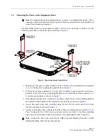
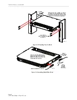
5 INSTALLING A RAPID FIBER PANEL WITHOUT EXTERNAL SPOOL
There are three main activities involved in installing a Rapid Fiber Panel without an external
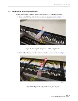
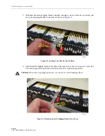
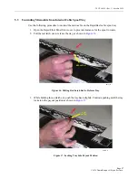
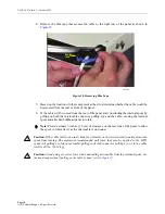
spool: mounting the panel on an equipment rack, removing the latch shipping brackets, and
unwinding the RapidReel cable spool tray. This section provides a procedure for each of these
activities.
Note:
The Rapid Fiber Panel is designed to be installed in an environmentally controlled
network telecommunications facility such as a Central Office, Controlled Environmental
Vault, or Data Center. Only the I/O cable is rated for both indoor and outdoor use.
Note:
When mounting multiple Rapid Fiber Panels into a rack or cabinet, be sure to
calculate the total weight of all the equipment being mounted to verify that it does not
exceed the rack or cabinet manufacturer’s maximum weight allowance. In Zone 4
Earthquake applications, exceeding the weight rating can compromise the integrity of the
rack during an earthquake.
Note:
Due to space constraints in conduit, only cables with MPO connectors or MPO-like
non-functional connectors should be routed through conduit.


