background image


860463082 

Issue 5, June 2014 

www.commscope.com


SYSTIMAX 360

™ 

iPatch

®

 Fiber Shelf with Faceplate 

Instructions 


© 2014 CommScope, Inc.  All rights reserved 


Page 1 of 13 


General 

The 

SYSTIMAX 360

™ 

iPatch

®

  G2  fiber  shelf with faceplate is a 

SYSTIMAX

®

  approved product. This 

distribution shelf provides for connection of non-metallic Outside Plant (OSP) cable or Lightguide Building Cable 

(LGBC) to 24 

iPatch

 LC duplex fiber ports either by direct termination or splicing. Designed for use in an 

iPatch


system, this shelf is one unit high and can be mounted in a standard 19-inch rack with a universal hole pattern. 

Both a sliding version and a fixed version are available. 

Note:

  To use the 

SYSTIMAX


360 iPatch

 G2 shelf in an existing 

iPatch

 system, the 

iPatch

 Managers must be 

running firmware version 8.1 or later, and the 

imVision

®

 Controller must be running firmware version 10.1 or 

later. The System Manager firmware, used to manage the system, must be Version 7.1 or later. We recommend 

that you upgrade the System Manager software to Version 7.1 or a later version before you install the shelf. 
Ordering information is listed below: 

Material ID 

Part No. 

Description 

760193789 

360-iP-G2-1U-LC-FX  

iPatch

®

 G2 LC fiber shelf, fixed 

760193797 

360-iP-G2-1U-LC-SD  

iPatch

®

 G2 LC fiber shelf, sliding


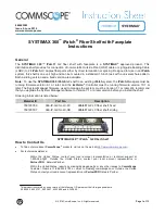
SYSTIMAX 360™ iPatch

®

 G2 Fiber Shelf 

How to Contact Us 

  To find out more about 

CommScope

® 

 products, visit us on the web at 

http://www.commscope.com/


  For technical assistance: 

-


Within the United States, contact your local account representative or technical support at  

1-800-344-0223. Outside the United States, contact your local account representative or 

PartnerPRO

 Network Partner. 

-


Within the United States, report any missing/damaged parts or any other issues to 

CommScope 

Customer Claims at 1-866-539-2795 or email to [email protected]. Outside the United 

States, contact your local account representative or 

PartnerPRO

 Network Partner. 


This product is covered by one or more of the following U.S. patents or their foreign equivalents:  

6,285,293, 6,522,737, 5,923,807, 6,245,998 and 8,344,900. 


Summary of Contents for 760193789

Page 1: ...must be Version 7 1 or later We recommend that you upgrade the System Manager software to Version 7 1 or a later version before you install the shelf Ordering information is listed below Material ID Part No Description 760193789 360 iP G2 1U LC FX iPatch G2 LC fiber shelf fixed 760193797 360 iP G2 1U LC SD iPatch G2 LC fiber shelf sliding SYSTIMAX 360 iPatch G2 Fiber Shelf How to Contact Us To fin...

Page 2: ...r fixed fiber tray LC duplex fiber faceplate 24 ports iPatch Ready LC fiber module plastic cover 1 Panel bus jumper 2 mounting brackets 2 3 inch storage drums 1 Patch cord trough 1 Hinged door for patch cord trough 4 12 24 x 1 2 inch screws for mounting the shelf in a 19 inch or 23 inch 584mm rack 2 Liquid tight cable fittings with lock nuts 2 Plastic cable tie retainers 6 Fiber type labels 4 labe...

Page 3: ...onized fiber optic cable which has a preferential bend axis Use caution to avoid kinking trunk cables iPatch high density fiber MPO adapters are equipped with protective dust caps installed in the front of all adapters Prior to installation clean the trunk cable and jumper connectors per the manufacturer s recommendations All wiring that connects to this equipment must meet applicable local and na...

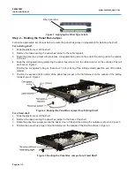
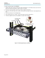
Page 4: ...etainer on the outside of the rail as shown in Figure 2 Position the corrugated tubing so that about 1 inch 2 5cm of the tubing extends past the end of the cable retainer 5 Position the exposed ribbon cable of the panel bus jumper in the flat retainers on the outside of the sliding rail as shown in Figure 2 Figure 2 Routing the Panel Bus Jumper for a Sliding Shelf For a fixed shelf 1 Slide the pla...

Page 5: ... x 3 8 inch screws included in the kit Mount the shelf to the rack using the four 12 24 screws provided For an ETSI rack use the 600 23BRKT accessory kit ordered separately and install one conversion bracket on one side of the shelf using two of the four 10 32 screws included in the kit Mount the shelf to the rack using four M6 x 12mm screws The shelf will not be centered in the rack Figure 4 Inst...

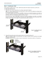
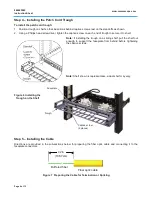
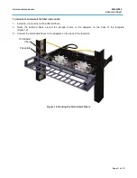
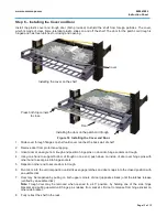
Page 6: ...trough to secure it to shelf Note If installing the trough on a sliding shelf pull the shelf out enough to support the faceplate from behind before tightening the captive screws Note Shelf shown is representative actual shelf may vary Figure 6 Installing the Trough on the Shelf Step 5 Installing the Cable Directions are provided in the sub sections below for preparing the fiber optic cable and con...

Page 7: ...he plastic plug from an appropriate cable entry hole in the back of the shelf 5 Feed the buffered fibers and the jacketed end of the cable through a round hole in the back of the shelf Figure 8 6 Unscrew the liquid tight lock nut and feed it through the selected cable entry hole to the inside of the shelf 7 Hold the liquid tight cable fitting so that the threaded portion is through the hole in the...

Page 8: ...ing V groove on the opposite side of the base Wearing safety glasses hold the base with a pair of pliers and grasp the breakaway tabs with another pair of pliers just above the V groove Figure 9 Bend the tab back and forth several times until it breaks off Repeat this process to remove the breakaway tabs on the opposite side of the base Use a file or sandpaper to smooth any rough edges that result...

Page 9: ...lices you are making splice the incoming buffered fibers to the pigtail 3 For fusion splices use your fingers to place the splices in the splice trays ordered separately in the recommended sequence shown in Figure 10 Note The numbers shown in Figure 10 do not appear on the actual splice trays For rotary mechanical splices use a 1012A compression tool to compress the springs on the splices and plac...

Page 10: ...htly to allow the rear latch to engage the splice tray 3 Push down on the splice tray at the rear latch until the splice tray snaps into position fully engaging the rear latch 4 Install the pivoting tray in the RoloSplice base 5 Dress the fibers as shown in Figure 11 and route the slack around the storage drums 6 Connect the pigtail connectors to the adapters on the back of the faceplate Figure 11...

Page 11: ...able 1 Install LC connectors on the buffered fibers 2 Route the buffered fibers around the storage drums to the adapters on the back of the faceplate Figure 12 3 Connect the terminated fibers to the adapters on the back of the faceplate Figure 12 Routing the Terminated Fibers Faceplate Terminated fibers ...

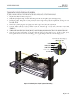
Page 12: ... a sliding shelf leave enough slack so that the cable moves freely when you slide the shelf out from the rack 3 Secure the incoming fiber optic cable to the back of the rack approximately 7 inches about 18cm above the shelf Figure 13 4 If the shelf is a sliding shelf slide the shelf out of the rack and back in making sure that it slides freely and the panel bus jumper does not bind Note The ribbon...

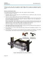
Page 13: ...ing one hand to support bottom of trough on one end push down on inside of door over hinge pins with other hand to seat pins into hinge sockets 5 Repeat on other end to secure door to trough 6 Pivot door into the vertical position until strikes engage latches and door snaps into the closed position with an audible click 7 Door may be reopened by pulling on both upper corners of door opposite strik...

Reviews: