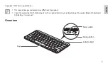
Commodore Amiga A1200, User Manual
The Commodore Amiga A1200, a classic gaming and productivity computer, is now available for download with its user manual for free. Learn all about this iconic machine and its capabilities by downloading the manual from our website. Unlock the full potential of the A1200 and enjoy hours of nostalgic gaming.
Share
Download


Reviews:
No comments
Related manuals for Amiga A1200
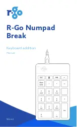
Numpad Break
Brand: R-Go Pages: 14
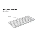
Compact
Brand: R-Go Pages: 11

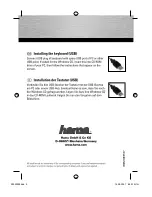
2100
Brand: Hama Pages: 10
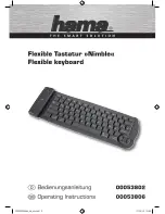
Nimble
Brand: Hama Pages: 10

98091
Brand: GE Pages: 9
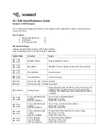
V3
Brand: WASD Pages: 4
Wireless Keyboard
Brand: Palm Pages: 20
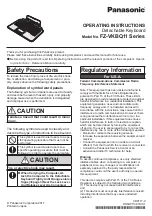
FZ-VKBQ11 Series
Brand: Panasonic Pages: 4
SXKC600 - ELECTRONIC KEYBOARD
Brand: Panasonic Pages: 48
VG-KBD2000
Brand: Samsung Pages: 10
EJ-BT230
Brand: Samsung Pages: 11
AK-120
Brand: Hama Pages: 2
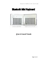
MiniPad
Brand: B-Speech Pages: 12
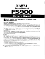
FS900
Brand: Kawai Pages: 48
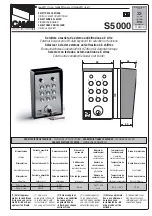
H SERIES
Brand: CAME Pages: 2
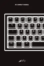
K5
Brand: Xtrfy Pages: 15
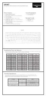
smart
Brand: Magicforce Pages: 2
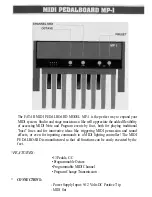
MP-1
Brand: Fatar Pages: 3


