background image

EN


22 


1


10


9


7


8


6


5


4


2


3


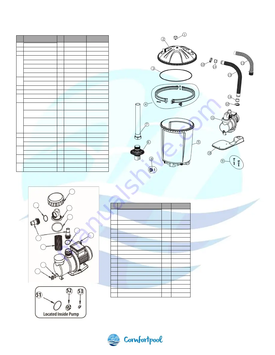
8.   Parts 

No.  Part 

Qty  Part no. 

For model 

Pressure gauge 

17001 

7000 & 9500 

Filter cover 

17003 

7000 & 9500 

O-ring 

17004 

7000 & 9500 

Left clamp ring 

L00169 

7000 & 9500 

Right clamp ring 

L00170 

7000 & 9500 

Clamp pin 

L00171 

7000 & 9500 

M8*80 bolt 

L00172 

7000 & 9500 

Plastic nut 

L00173 

7000 & 9500 

Filter tank 

1701025 

7000 

Filter tank 

1701050 

9000 

Basket filter 

17011 

7000 & 9500 

Hard tube 

17012 

7000 & 9500 

Drain valve 

17013 

7000 & 9500 

O-ring 

17014 

7000 & 9500 

Pump bolt wing nut 
PUMP MOUNTING  

P00175 

7000 & 9500 

Pump bolt flat water 
PUMP MOUNTING 

P00176 

7000 & 9500 

Pump bolt lock washer 
PUMP MOUNTING 

P00177 

7000 & 9500 

Pump bolt nut 
PUMP MOUNTING  

P00178 

7000 & 9500 

10  Base plate 

17019 

7000 & 9500 

11 

Water pump 1/2hp 

SPS1A450 

7000 

Water pump 3/4hp 

SPS1A550 

9000 

12 

Hose clamp 

17021 

7000 

Hose clamp 

17021 

9000 

13 

Soft hose 

1702225 

7000 

Soft hose 

1702250 

9000 

14 

Hose reducer 

17023 

7000 

Hose reducer 

17023 

9000 


No.


Part


Qty


Partno. 


1


Water pump/ motor 

1


SPS1A250 
SPS1A450 
SPS1A550


2


Transparent hair & lint strainer 

1


P00131


3


11/4"- 1 1/2" hose connector 

2


P00132


4


O-ring "A"- 2 1/4" 

1


P00182


5


O-ring "B"- 3" 

1


P00183


6


O-ring "C"- 1.5" 

1


P00184


7


Strainer collar 

1


P00133


8


Strainer basket 

1


P00134


9


Pump drain cap 

1


P00135


10


Drain valve O-ring 

1


P00136


11


Motor pump seal 

1


P00137


11


Motor pump seal 

1


P00138


11


Motor pump seal 

1


P00138


12


Impeller assembly 

1


P00139


12


Impeller assembly 

1


P00140


12


Impeller assembly 

1


P00140


13


Shaft seal & spring assembly 

1


P00141


13


Shaft seal & spring assembly 

1


P00142


13


Shaft seal & spring assembly 

1


P00142


Summary of Contents for FuzzyClean 7000

Page 1: ...FuzzyClean 7000 9500...

Page 2: ...g __________________________________________________________________7 3 Gebruiksinstructies __________________________________________________________________7 3 1 Opstarten van de filterpomp ________...

Page 3: ...mogelijke elektrische schok te voorkomen mag u de stekker niet in het stopcontact steken of uit het stopcontact halen wanneer u natte handen heeft of met uw voeten in het water staat Plaats de filterp...

Page 4: ...et een tankafvoersysteem De filtertank wordt gebruiksklaar geleverd met een goedgekeurde filterpomp met haar en pluisjesmand en een plastic basis voor montage ter plaatse Lees deze handleiding zorgvul...

Page 5: ...an de filterpomp Haal het product en alle onderdelen voorzichtig uit de doos Kruis alle onderdelen in de doos aan met de referentietabel van de onderdelenlijst om er zeker van te zijn dat alle onderde...

Page 6: ...buitenste opening van de pomp 4 Plaats O ring B in de groef rond de haar en pluiszeefmand 5 Plaats het transparante deksel van de haar en pluiszeef op zijn plaats en schroef de ring met schroefdraad k...

Page 7: ...ructies Zodra het filtersysteem correct is gemonteerd de tank gevuld is met filterbollen en de slangen zijn aangesloten zoals hierboven beschreven kunt u beginnen met filteren 3 1 Opstarten van de fil...

Page 8: ...aan de filterbollen wat resulteert in een aanzienlijke vermindering van het filtervermogen Bovendien kan mogelijke schade aan de filtertank of zijn interne componenten optreden Comfortpool is niet ve...

Page 9: ...et schoonmaken van de filterbollen Vul de tank met enkele centimeters water ongeveer 1 8 van de tankhoogte terwijl de filterbollen worden schoongemaakt Installeer en reinig de katoenen staarten met de...

Page 10: ...NL 10 7 Installatie illustraties...

Page 11: ...00 10 Bodemplaat 1 17019 7000 9500 11 Waterpomp PK 1 SPS1A450 7000 Waterpomp PK 1 SPS1A550 9000 12 Slangklem 1 17021 7000 Slangklem 2 17021 9000 13 Flexibele slang 1 1702225 7000 Flexibele slang 1 170...

Page 12: ...sing een ongeluk onjuist gebruik verkeerde stroomtoevoer ander gebruik dan in de handleiding beschreven staat en onjuist onderhoud of opslag Indien de filterpomp onderhevig is aan schade veroorzaakt d...

Page 13: ...ion _________________________________________________________________17 3 Operation instructions ________________________________________________________________18 3 1 Filter system start up__________...

Page 14: ...do not plug in or unplug the power cord when your hands are wet or when you are standing in water Never place or submerge the filter pump in water Before cleaning or moving the filter pump or pool al...

Page 15: ...in effect for the area of installation We decline all responsibility for the consequences of failure to comply with the installation instructions We recommend that you comply with the power source in...

Page 16: ...parts diagram 1 4 Power source instructions The filter pump system you have purchased is equipped with a standard electrical cord and plug which should only be connected to a power outlet protected b...

Page 17: ...around the top of the filter tank is in good condition and securely seated in the groove Be sure groove is free of sand Carefully place the tank cover onto the filter tank The tank cover should be ori...

Page 18: ...the filter pump system installed in a location level lower than your pool s water level water will automatically flow into the filter pump Allow the filter tank to fill with water 3 Check the filter...

Page 19: ...ntil the pool vacuum is connected and ready for operation IMPORTANT The pool vacuum hose must be fully filled with water so that the pump does not lose prime and fill the tank with air 5 Winterizing a...

Page 20: ...ring immediately Do not back wash on initial installation No need to back wash unless tank s pressure gauge reaches 25 PSI We recommend removing filter balls from filter tank at end of the season plac...

Page 21: ...EN 21 7 Installation illustration...

Page 22: ...00178 7000 9500 10 Base plate 1 17019 7000 9500 11 Water pump 1 2hp 1 SPS1A450 7000 Water pump 3 4hp 1 SPS1A550 9000 12 Hose clamp 1 17021 7000 Hose clamp 2 17021 9000 13 Soft hose 1 1702225 7000 Soft...

Page 23: ...y does not apply in the following circumstances If the filter pump is subject to negligence abnormal use or application accident improper operation improper voltage or current contrary to operating in...

Reviews: