23
EN
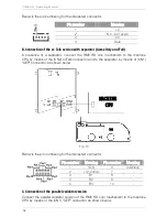
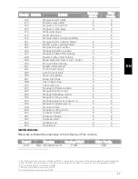
Below is the pin numbering for the interested connector :
Pin number
Meaning
1
+V
2
N.V.
3
0 V
4
Date
I. CN3 USB connector (optional)
When installed, it allows connecting the coin mechanism to boards or to a PC by
means of a USB cable.
L. LED
All RM5 HD coin mechanisms are equipped with a led, which provides the following
information on the status and diagnostics through light pulses.
Light indication
Meaning
2 red pulses and 2 green pulses
ON
Red flashing
A problem occurred
Orange pulse
Recognised coin but not enabled
Green pulse
Recognised coin accepted
Red pulse
Coin recognised as false and discarded
6. Settings
6.1. Configuration
Configurating the RM5 HD coin mechanism means setting the operation mode most
suited to the user’s requirements. Configuration allows, for example, carrying out
operations such as self-learning, modifying dip switches or some operating
parameters
RM5 HD can be configured by means of the mobile Virtual Dip Switch device for a
basic configuration, or by means of the PC Multiconfig configuration programme,
which allows a complete configuration in all aspects.
A. Configuration by means of VIRTUAL DIP SWITCH (optional)
RM5 HD can be configured on the field using the Virtual Dip Switch, by connecting the
latter to the “PRG” (3) connector and following the instructions provided.
Virtual Dip Switch is a mobile device that allows carrying out the basic configuration
functions directly on the field without having to disinstall the coin mechanism from the
machine.
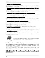
Thanks to its button and LED graphical interface, the Virtual Dip Switch allows:
•
Enabling/disabling all the coins with the same value
Allows activating or deactivating the acceptance of one or more coins.
Summary of Contents for RM5 HD
Page 2: ......
Page 16: ...RM5 HD Operating Manual 16 Fig 6 B 2 Front panel F6 Fig 7...
Page 37: ...37 EN...
Page 38: ...RM5 HD Operating Manual 38...
Page 39: ...39 EN...


