background image

ECON-4 1.4.0 Global Guide

60

Setpoint group

Main PID

Related FW

1.4.0

configured ECON-4

ADV extension module

Range [units]

0 – 100.0 %

Default value

40%

Force value

NO

Step

0.1 %

Comm object

13980

Related applications

ALL

Setpoint visibility

WinScope only

Description

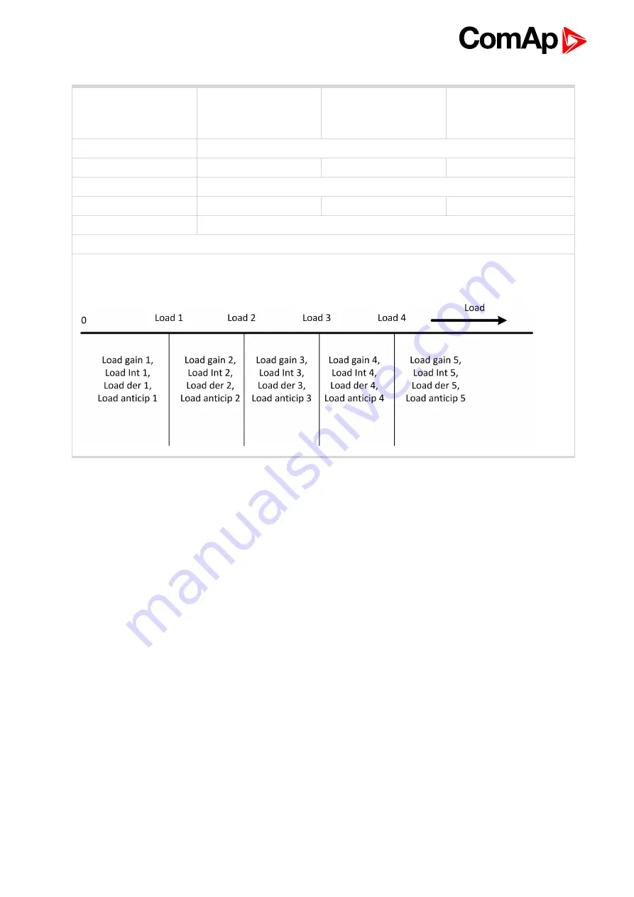
There is 5 load bands defined via setpoints

Load 1

to

Load 5

and different

Load gain

,

Load Int

,

Load der

and

Load anticip

setpoints are active in each band.

Load 2

6

back to List of setpoints

Summary of Contents for ECON-4

Page 1: ...ue 7 Czech Republic Tel 420 246 012 111 E mail info comap cz www comap control com Global Guide ECON 4 Digital Speed Governor SW version 1 4 0 1 Document information 4 2 System overview 7 3 Applications overview 8 4 Installation and wiring 9 5 ECON 4 setup 22 6 Communication 40 7 Technical data 41 8 Appendix 43 ...

Page 2: ...sions and mounting 10 4 3 Jumper position 11 4 4 Recommended wiring 12 4 4 1 General 12 4 4 2 Grounding 13 4 4 3 Power Supply 13 4 4 4 Binary inputs 13 4 4 5 Analog inputs 15 4 4 6 Analog output 17 4 4 7 Interface to actuators 18 4 4 8 Speed Pick up 20 4 4 9 Communication wiring 20 5 ECON 4 setup 22 5 1 Quick start how to set ECON4 and controller 22 5 1 1 Breakers feedback handling CB request mode...

Page 3: ... for BRIDGE actuator type typically Heinzmann 35 5 6 Detailed fucntion 37 5 6 1 Block schematics speed governor 37 6 Communication 40 6 1 Connection to ECON 4 40 7 Technical data 41 8 Appendix 43 8 1 Setpoints 44 8 1 1 List of setpoint groups 44 8 1 2 List of setpoints 45 8 1 3 Group Engine StartGroup ECON4 EngRPM 46 8 1 4 Group Engine StartGroup ECON4 EngStart 51 8 1 5 Group Main PIDGroup ECON 4 ...

Page 4: ...and or in the Standardní podmínky projektů komplexního řešení ke smlouvě o dílo Standard Conditions for Supply of Complete Solutions Conditions as applicable ComAp s License Agreement is governed by the Czech Civil Code 89 2012 Col by the Authorship Act 121 2000 Col by international treaties and by other relevant legal documents regulating protection of the intellectual properties TRIPS The End Us...

Page 5: ...ch verification must be agreed in the written form and in advance For more details relating to the Ownership Extent of Permitted Reproductions Term of Use of the Documentation and to the Confidentiality rules please review and comply with the ComAp s License Agreement Terms and Conditions available on www comap control com ...

Page 6: ...e Connector male Controller simplified ECON 4 simplified Fuel solenoid Fuse Fuse switch Generator Generator schematic Grounding Jumper Load Mains Mains Pick up Resistor Resistor adjustable RS 232 female Starter Voltage measureme nt ECON 4 1 4 0 Global Guide 6 ...

Page 7: ...n case of actuator with 0 20mA 4 20mA usage This actuator can control a fuel rack for diesel engines or a mixture throttle valve for gas engines ECON 4 ADV is advanced version it is dedicated specially to control of engine in island operations where load steps are expected 2 1 1 Control by CAN bus ECON 4 can receive values of some binary and analog control inputs via CAN bus communication line fro...

Page 8: ...ECON 4 1 4 0 Global Guide 8 3 Applications overview 3 1 Wiring overview 6 back to Table of contents ...

Page 9: ...e 9 4 Installation and wiring 4 1 Package content 9 4 2 Module installation 10 4 3 Jumper position 11 4 4 Recommended wiring 12 6 back to Table of contents 4 1 Package content The package contains ECON 4 module Terminal blocks ...

Page 10: ...ECON 4 1 4 0 Global Guide 10 4 2 Module installation 4 2 1 Dimensions and mounting Image 4 1 Dimensions terminals and mounting Note ECON 4 unit is mounted on DIN rail 35 mm ...

Page 11: ...3 Jumper position Jumper Meaning P6 AOUT switch between current and voltage analogue output Current link the 2 pins from right side Voltage link the 2 pins from left side P7 120 Ohm resistor for CAN line termination P9 Boot P10 Reset ...

Page 12: ...Magnetick Pick up Speed Pick up page 20 Analog outputs Analog output page 17 Communications Communication wiring page 20 6 back to Installation and wiring 4 4 1 General Use grounding terminals The terminal of the battery has to be properly grounded Cables for binary inputs and analogue inputs must not be placed along power cables Analogue inputs should use shielded cables especially when length 3m...

Page 13: ...supply terminals are protected against large pulse power disturbances When there is a potential risk of the controller being subjected to conditions outside its capabilities an outside protection device should be used Power Supply Fusing An eight amp fuse should be connected in line with the battery positive terminal to the controller and modules ECON 4 should never be connected directly to the st...

Page 14: ...munication on CANbus all bits of the byte Command are set to 0 it deactivates MCB fdb S4 1 Inputs GCB and MCB fdb decide which setpoints are used in PID speed regulation loop and which type of regulation is used Iddle Island Parallel MCB state GCB state lRPM Requested RPMl RPM window PID constants OFF OFF NO Speed gain Speed int Speed der OFF OFF YES Speed gain Speed int w Speed der w ON OFF NO Sp...

Page 15: ...uts SPEED UP and SPEED DOWN are active only if the setpoint Speed request has value BIN SPEED DOWN S4 5 Inputs SPEED UP and SPEED DOWN are used for setting of the speed reference of the engine The speed reference can be changed in the range from Nominal RPM PerChSpdNom to Nominal RPM PerChSpdNom Setpoint EngineRPM PerChSpdNom 1 20 defines the maximum Percentage change of Speed from Nominal in case...

Page 16: ... power Value of the Active power is used to improve load step response of the governor Input ACTIVE POWER is active only if the setpoint Speed request has not value DATA The input sensitivity can be adjusted by setpoint Load anticip Note Input ACTIVE POWER is active only if the setpoint Speed request has value BIN or ANA and setpoint Load anticip 0 Collaboration with ECON 4Slave Physical analog in...

Page 17: ...o ACT output GAS DOSE Analogue output range is fully programmable in range 0 10V or 0 20mA see setpoints Analog settings AOUT 0 and AOUT 100 Range Recommended wiring Output Terminals Jumpers 0 20 mA AOUT S6 1 S6 2 P6 20 mA 0 10 V AOUT S6 1 S6 2 P6 10 V Gas Dose S6 1 Output signal corresponds to actuator requested position The limits are fully scaleable in range 0 10V 0 20mA E g an actuator with in...

Page 18: ...ommended to connect PWM output by a twisted cable and connect feedback input by a shielded cable Range Recommended wiring Terminals Jumpers Ooutput 0 8 A S1 3 Feedback 0 5 V S2 2 S2 1 S2 3 P21 5V Feedback 0 10 V S2 2 S2 1 S2 3 P21 10V Types of actuators supported by ECON 4 With current input 200mA Example Typical example is Woodward UG A It is electro hydraulic actuator in principle a small electr...

Page 19: ... ActType Wiring LINEAR or LINEAR NO FEEDBACK Motor driven actuators Example Typical examples are actuators from Heinzmann STG 6 10 30 2040 It is in principle a DC electromotor driving actuator lever Since it is a motor it has integrating characteristic as long as the current flows through the actuator actuator s lever moves Direction of movement of the actuator lever depends on polarity of the cur...

Page 20: ...nd SIG are separated from all other terminals This enables to share one pick up by two modules for instance by a speed governor and by an ignition without danger of creating a ground loop 4 4 9 Communication wiring CAN bus connection ECON 4 is equipped by CAN communication line CAN bus terminals are electrically isolated from any other terminals Note Following ECON 4 CAN setting is necessary to co...

Page 21: ...es both ends must be by the 120 ohm internal or external resistor terminated Maximal CAN bus length is 200 meters ECON 4 contains internal 120 ohm resistor connected through a removable jumper P7 For CAN data cables details see chapter Technical data Communication interface CAN cable shielding connect to CAN COM terminal 6 back to Recommended wiring ...

Page 22: ...ata from CAN1 line Input signals of ECON4 are separated in to two groups each group can be controlled in different way Group Setpoint Signal Possible control mode Breaker s feedback CB request GCB feedback BIN ANA DATA MCB feedback Speed control Speed request Speed request analogue signal BIN DATA Actual power analogue signal SpeedUp and SpeedDown binary signal Idle Nominal binary signal Droop bin...

Page 23: ...ary outputs of ECON4 in Genconfig CB request set to DATA mode Image 5 2 CB request DATA mode In case of DATA control of breaker s feedback logical signals from breakers has to be linked to Binary outputs of ECON4 in Genconfig Terminals S4 1 and S4 2 do not need to be wired 5 1 2 Speed control handling Speed request modes Speed request set to ANA mode Image 5 3 Speed request ANA mode ...

Page 24: ...s fully controlled via binary inputs terminals S4 3 S4 8 except CB control The input S4 6 is the ON OFF signal to ECON 4 in case it is not active speed governor will not open the throttle In case it is deactivated during engine running throttle is immediately closed Use BIN S4 3 to switch from Idle running to Nominal speed running Idle and Nominal speed adjustment is in ECON 4 setpoints Engine RPM...

Page 25: ...scribed in previous chapter Breaker s feedback handling CB request modes BO3 Idle Nominal configure on this output signal which defines switching from Idle operation to Nominal ROM run The Log bout signal Idle Nominal of IGS NT can be used In case the Idle period is required to be skipped configure on this output signal Log bout Logical 1 BO4 Run Stop together with binary input S4 6 RUN STOP this ...

Page 26: ...M pick up Sensor Electronic the IGS NT controller d Configuration of Analogue outputs from IGS NT to ECON 4 AOUT1 Active Power Rel ECON 4 is equipped with the Load anticipation function to react as quickly as possible to the sudden changes of the engine power For this function ECON 4 needs information about power and in case of DATA mode this can be sent to ECON 4 via CAN Adjust the AOUT1 in the f...

Page 27: ...d ctrl Freq int 5 Sync Load ctrl Angle gain 10 IMPORTANT Please take in account there are several setpoints of ECON 4 which are not accessible via IGS NT control unit in case of DATA mode These parameters are crucial for ECON 4 and used Actuator adjustment and so these are accessible via ECON 4 connection ONLY Use ComAp PC sw WinScope to adjust these setpoints For all modes of ECON 4 usage adjust ...

Page 28: ...se see GenConfig Global Guide 5 3 Data Following data are communicated between IS NT specific sw branches only and ECON 4 via CAN bus Correct function depends on configuration by PC GenConfig software 5 3 1 Data Binary inputs Following data from ECON 4 can be used for states indication or alarms activation ECON 4 Name Function BI1 Bin1 Physical input state reserve BI2 Bin2 GCB Fdbck Physical input...

Page 29: ... IS NT AI2 Misfiring Amplitude1 No RPM pickup is needed in IS NT Configure IS NT I O ECON 4 AIN1 Engine RPM for Function RPM pick up Sensor Electronic 5 3 4 Data Analog outputs ECON 4 Name Function AOUT1 Active power relative 0 0 100 0 option AOUT2 SpeedReq RPM In RPM 8 option Active power value is required for Load anticipation function see Main PID Load anticip In GenConfig choose value Gener va...

Page 30: ...Cur 0 and ActCur 100 are not used so their value is not important G Parameters ActTypex In this case ActType 1 Act MaxCur is maximum allowable current in case bigger current is detected in fact bigger output PWM signal is detected for longer then ActMaxCurDel then the output is limited to value ActReduced Cur So in case we have actuator with resistance 32Ohms ECON power supply is 24Volts and maxim...

Page 31: ...t parameter Main PID ECON 4 mode to AUTOMATIC J Based on the chosen type of control BIN ANA DATA connect the required signal K Adjust all other parameters like Nominal Idle speed Geer teeth Overspeed Speed and Load PID ActChannel to the number which ECON 4 output you are using L ECON 4 is ready for start attempt Adjustment for BRIDGE actuator type typically Heinzmann A At first check the position ...

Page 32: ...red response L After adjustment is finished put parameter Main PID ECON 4 mode to AUTOMATIC M Based on the chosen type of control BIN ANA DATA connect the required signal N Adjust all other parameters like Nominal Idle speed Geer teeth Overspeed Speed and Load PID ActChannel to the number which ECON 4 output you are using O ECON 4 is ready for start attempt 5 4 ECON 4 configuration and PC tools 5 ...

Page 33: ...ommon for ECON 4 Tick the button Program and choose the appropriate firmware using icon Locate You can save your setpoints from an existing site and program them together with the new firmware However the program change does not influence the setpoints so you can keep them in ECON 4 Choose the right COM port number and press Start button Hint ...

Page 34: ...by resistance of the actuator and power supply of ECON 4 ECON 4 is rated to maximum 8 Amps In case the actuator has resistance 32 Ohms and power supply is 24V then maximum ECON 4 current is 24 32 0 75A 750mA This means 100 of ECON current is 750mA In case the maximum allowable actuator current is 250mA then this is 33 3 of maximum ECON 4 current This value will be used for the maximum current limi...

Page 35: ...n this case ActType 1 Act MaxCur is maximum allowable current in case bigger current is detected in fact bigger output PWM signal is detected for longer then ActMaxCurDel then the output is limited to value ActReduced Cur The Act Max Curr is calculated from the value Act Cur 100 so it means that the current limitation is in this case already done by adjustment of ActCur 100 and Act Max Cur shall b...

Page 36: ...ActMaxCurDel then the output is limited to value ActReduced Cur F Adjust parameter Wiring to BRIDGE and adjust parameters Act gain to 10 Act int to 10 and Act der to 10 G Parameters ActTypex In this case ActType 1 ActCur 0 and ActCur 100 are not used so their value is not important H Adjust parameter Main PID Actuator Type to the actuator which you use so in this case ActType 1 I Connect the actua...

Page 37: ...nd operation Overspeed protection In case the actual RPM crosses RPM value Engine RPM Overspeed then the Gas Dose is immediately forced to the zero throttle is closed and shutdown is issued There is proactive action taken to try to keep engine running without shutdown when actual RPM reaches value in the middle between Nominal and Overspeed value In this case when RPM crosses this middle value Gas...

Page 38: ...ivative parts The PID setpoints Gain Int and Der define the quality of regulation The parameters of the PID control structure are different if the engine is in no load operation loaded operation For more information see setpoint Description page 53 The output of the PID control structure is then added together with the Load anticipation feedback which is directly proportional to the engine power T...

Page 39: ... speed request is in Bias position because no power control has been done in previous stage So there is difference between actual speed request and speed request corresponding to actual throttle position This difference is called Speed request offset and we keep it to make transition burpless When controller increase aped request to provide more power to Mains we move throttle to higher position o...

Page 40: ...onnection to ECON 4 Connect RS232 cable and start WinScope software Click on the Connection Open Connection and choose Direct connection type EmCon5 ECON 4 INCON Controller type choose the right COM port and press O K button 6 back to Table of contents ...

Page 41: ...t resistance 4 4 kΩ Input range 0 36 V DC Switching voltage level for close contact indication 0 2 V Max voltage level for open contact indication 8 36 V Binary inputs Maximal CAN bus length 200 m galvanically separated Speed 250 kBd Nominal impedance 120 Ω Cable type twisted pair shielded CAN bus interface Weight 600 g Protection IP20 General information Operating temperature 30 to 70 C Storage t...

Page 42: ... bps RS232 interface Type of sensor Active or magnetic pick up connection by shielded cable is strongly recommended Minimum input voltage 2 Vpk pk from 4 Hz to 4 kHz Maximum input voltage 50 Veff Minimum measured frequency 4 Hz Maximum measured frequency 10 kHz min input voltage 6Vpk pk Frequency measurement tolerance 0 2 Speed pick up inputs 6 back to Table of contents ...

Page 43: ...ECON 4 1 4 0 Global Guide 43 8 Appendix 8 1 Setpoints 44 6 back to Table of contents ...

Page 44: ...r and modify a password IMPORTANT Setpoints are organized in logical groups for better orientation Use WinScope or InteliMonitor software to modify the setpoints For details see chapter ECON 4 configuration and PC tools page 32 8 1 1 List of setpoint groups 8 1 3 Group Engine StartGroup ECON4 EngRPM 46 8 1 4 Group Engine StartGroup ECON4 EngStart 51 8 1 5 Group Main PIDGroup ECON 4 MainPID 53 8 1 ...

Page 45: ...d 1 59 Load 2 60 Load 3 61 Load 4 62 LAder limit 67 LAder limit 67 LAder 67 LAder 68 LAder recover 68 LAder recover 68 Group of setpoints Analog sensors LoReqSpeed Inp 72 HiReqSpeed Inp 72 AOUT 0 73 AOUT 100 73 FBD 0 pos 73 FBD 100 pos 74 Group of setpoints ActType 1 2 3 4 Act gain 69 Act int 69 Act der 69 Act MaxCur 70 ActmaxCurDel 70 Act ReducedCur 70 Wiring 71 6 back to Setpoints ECON 4 1 4 0 G...

Page 46: ...PM Default value 1500 RPM Force value NO Step 1 RPM Comm object 7187 Related applications ALL Setpoint visibility Always Description Nominal engine speed Nominal RPM 6 back to List of setpoints Setpoint group Engine RPM Related FW 1 4 0 configured ECON 4 extension module Range units 0 2500 RPM Default value 1800 RPM Force value NO Step 1 RPM Comm object 7168 Related applications ALL Setpoint visib...

Page 47: ...ngine RPM Related FW 1 4 0 configured ECON 4 extension module Range units 0 100 s Default value 10 s Force value NO Step 1 s Comm object 7169 Related applications ALL Setpoint visibility Always Description Define how fast changes the requested engine speed during transition from Idle RPM page 46 to Nominal RPM page 46 and vice versa Idle Nom ramp is directly time that the ramp needs to go from Idl...

Page 48: ...elated applications ALL Setpoint visibility Always Description Define how fast changes the requested engine speed if the binary inputs SPEED UP or SPEED DOWN are active BI Speed ramp is actually time that the ramp needs to go from Nominal RPM page 46 8 toNominal RPM page 46 8 and vice versa The ramping speed is the same for both up and down directions BI Speed ramp 6 back to List of setpoints ...

Page 49: ...e value NO Step Comm object 7171 Related applications ALL Setpoint visibility Always Description The setpoint defines source of the Speed reference of the engine Speed Request value Speed reference source BIN SPEED UP SPEED DOWN ANA SPEED REQUEST DATA CAN bus Speed request BIN Speed request ANA Speed request DATA Speed request 6 back to List of setpoints ...

Page 50: ... assure fastest reaction of ECON4 when breaker is closed or opened This is crucial to avoid over speed in case of opening GCB under load for example CB request 6 back to List of setpoints Setpoint group Main PID Related FW 1 4 0 configured ECON 4 ADV extension module Range units Nominal RPM Overspeed RPM Default value 1750 Force value NO Step 1 RPM Comm object 14408 Related applications ALL Setpoi...

Page 51: ...d fulfill the most of installations PerChSpdNom 6 back to List of setpoints Setpoint group Main PID Related FW 1 4 0 configured ECON 4 ADV extension module Range units IDLE FUEL CLOSE Default value Force value NO Step Comm object 14409 Related applications ALL Setpoint visibility WinScope only Description Value set to output GAS Dose when RPM reaches value in setpoint PreOverSpeed PreOverSpReduct ...

Page 52: ...RPM Default value 10 s Force value NO Step 1 s Comm object 7174 Related applications ALL Setpoint visibility Always Description Time the actuator needs to move from the InitStart dose to MaxStart dose Fuel ramp time 6 back to List of setpoints Setpoint group Engine RPM Related FW 1 4 0 Range units Start RPM Nominal RPM Default value 10 s Force value NO Step 1 s Comm object 7175 Related application...

Page 53: ... Nominal RPM If this condition is not met ECON 4 activates bit Invalid setpoints in Transmit PDO 1 see description of CAN protocol It is not possible to run the engine if the bit Invalid setpoint is signalized 6 back to List of setpoints 8 1 5 Group Main PIDGroup ECON 4 MainPID Setpoint group Main PID Related FW 1 4 0 configured ECON 4 extension module Range units 0 0 200 0 Default value 10 Force ...

Page 54: ...f the PID speed regulation loop Speed int Note Setpoint is active for unloaded engine 6 back to List of setpoints Setpoint group Main PID Related FW 1 4 0 configured ECON 4 extension module Range units 0 0 100 0 Default value 0 Force value NO Step 0 1 Comm object 7178 Related applications ALL Setpoint visibility Always Description Derivative part of the PID speed regulation loop Speed der Note Set...

Page 55: ...ow 6 back to List of setpoints Setpoint group Main PID Related FW 1 4 0 configured ECON 4 extension module Range units 0 100 Default value 10 Force value NO Step 1 Comm object 12092 Related applications ALL Setpoint visibility WinScope only Description Integration part of the PID regulation loop in case the actual RPM differs from Requested RPM for more than RPM window Speed int w 6 back to List o...

Page 56: ...For more information about Load der setting please see Load 1 page 59 ECON 4 Global Guide Load gain 6 back to List of setpoints Setpoint group Main PID Related FW 1 4 0 configured ECON 4 extension module Range units 0 0 100 0 Default value 0 Force value NO Step 0 1 Comm object 7181 Related applications ALL Setpoint visibility Always Description Derivative part of the PID speed regulation loop Ther...

Page 57: ...alue NO Step 0 1 Comm object 7180 Related applications ALL Setpoint visibility Always Description Integration of the PID speed regulation loop There is 5 different setpoints Load Int Load Int 1 Load Int 2 Load Int 3 Load Int 4 For more information about Load Int setting please see Load 1 page 59 ECON 4 Global Guide Load Int 6 back to List of setpoints ...

Page 58: ...ad anticip setting Engine load value can be received via physical Analog input S3 2 ACTIVE POWER as 0 to 10V or 20 mA signal if setpoanticip Speed request BIN or ANA or via CAN bus in the case of communication to IS NT controller if setpoanticip Speed request DATA In such case follow this configuration in GenConfig I O Analog outputs ECON 4 AOUT1 Gener values Act power rel In the configuration cho...

Page 59: ...100 0 Default value 20 Force value NO Step 0 1 Comm object 13979 Related applications ALL Setpoint visibility WinScope only Description There is 5 load bands defined via setpoints Load 1 to Load 5 and different Load gain Load Int Load der and Load anticip setpoints are active in each band Load 1 6 back to List of setpoints ...

Page 60: ...100 0 Default value 40 Force value NO Step 0 1 Comm object 13980 Related applications ALL Setpoint visibility WinScope only Description There is 5 load bands defined via setpoints Load 1 to Load 5 and different Load gain Load Int Load der and Load anticip setpoints are active in each band Load 2 6 back to List of setpoints ...

Page 61: ...100 0 Default value 60 Force value NO Step 0 1 Comm object 13981 Related applications ALL Setpoint visibility WinScope only Description There is 5 load bands defined via setpoints Load 1 to Load 5 and different Load gain Load Int Load der and Load anticip setpoints are active in each band Load 3 6 back to List of setpoints ...

Page 62: ...ifferent Load gain Load Int Load der and Load anticip setpoints are active in each band Load 4 6 back to List of setpoints Setpoint group Main PID Related FW 1 4 0 configured ECON 4 extension module Range units 0 0 100 0 Default value 0 Force value NO Step 0 1 Comm object 7182 Related applications ALL Setpoint visibility Always Description Droop of speed governor The governor lovers the speed refe...

Page 63: ...is also used as coordinate for Speed Fuel line See description in chapter Speed governor function in parallel mode 6 back to List of setpoints Setpoint group Main PID Related FW 1 4 0 configured ECON 4 extension module Range units 0 0 100 0 Default value 10 Force value NO Step 0 1 Comm object 7192 Related applications ALL Setpoint visibility Always Description IdleFuel is base together with MaxFue...

Page 64: ...ule Range units Default value AUTO Force value NO Step Comm object 7190 Related applications ALL Setpoint visibility Always Description ECON 4 must be in AUTO for normal operation Mode MAN can be used during installation to check the function of the actuator and linkage If ECON 4 is in MAN mode it sets the actuator to position Act position It can be switched to MAN mode only any time even engine i...

Page 65: ...ility Always Description Frequency of the PWM signal sent to ACT and ACT outputs PWM rate Note For Heinzmann actuators adjust the PWM rate to 6000 Hz For Woodward PWM and current GAC actuators adjust the PWM rate to 2000Hz 6 back to List of setpoints Setpoint group Main PID Related FW 1 4 0 configured ECON 4 extension module Range units 10 V Default value 0 00 V Force value NO Step 0 01 V Comm obj...

Page 66: ...e on page 38ECON 4 Global Guide SGO HiLim Note Setpoint is active for unloaded engine 6 back to List of setpoints Setpoint group Main PID Related FW 1 4 0 configured ECON 4 extension module Range units 10 1800 s Default value 30 s Force value NO Step 1 s Comm object 14375 Related applications ALL Setpoint visibility Undefined variable Specific WinScopeOnly Description This defines ramp according S...

Page 67: ...1 4 0 configured ECON 4 ADV extension module Range units 0 100 0 Default value 5 Force value NO Step 0 1 Comm object 14405 Related applications ALL Setpoint visibility WinScope only Description Limit on Load step in direction changes bellow this limit will not generate any derivation LAder limit 6 back to List of setpoints Setpoint group Main PID Related FW 1 4 0 configured ECON 4 ADV extension mo...

Page 68: ...04 Related applications ALL Setpoint visibility WinScope only Description Derivation curve definition drop from value Initial value is divided by this number repeatedly once per 0 1s So higher value means faster drop to zero LAder recover 6 back to List of setpoints Setpoint group Main PID Related FW 1 4 0 configured ECON 4 ADV extension module Range units 1 01 10 00 Default value 10 Force value N...

Page 69: ... 1 Comm object 11109 Related applications ALL Setpoint visibility WinScope only Description Gain of the PID actuator position control loop Act gain 6 back to List of setpoints Setpoint group ActType 1 2 3 4 Related FW 1 4 0 Range units 0 1000 Default value 20 Force value NO Step 1 Comm object 11110 Related applications ALL Setpoint visibility WinScope only Description Integration factor of the PID...

Page 70: ...4 0 Range units 0 0 300 0 s Default value 5 s Force value NO Step 0 1 s Comm object 11113 Related applications ALL Setpoint visibility WinScope only Description Actuator Overload protection limit delay ActmaxCurDel 6 back to List of setpoints Setpoint group ActType 1 2 3 4 Related FW 1 4 0 Range units 0 0 100 0 Default value 40 Force value NO Step 0 1 Comm object 11114 Related applications ALL Set...

Page 71: ...xample it is electro hydraulic actuator in principle a small electromagnetic actuator with hydraulic booster It has unipolar proportional characteristic the bigger is the current the bigger is the angle of the actuator Direction of movement of the actuator lever does not depend on polarity of the current Actuator is without position feedback Wiring 6 back to List of setpoints 8 1 7 Act type 2 pred...

Page 72: ...etpoint structure see Act type 1 predefined for Woodward ITB 0 200 mA on page 69 6 back to List of setpoints 8 1 10 Group Analog sensors Setpoint group Analog sensors Related FW 1 4 0 configured ECON 4 extension module Range units Range 0 0 100 0 Default value 0 0 Force value NO Step 0 1 Comm object 11125 Related applications ALL Setpoint visibility WinScope only Description Value of analog input ...

Page 73: ... Comm object 11645 Related applications ALL Setpoint visibility WinScope only Description Analogue output high limit signal definition AOUT 100 6 back to List of setpoints Setpoint group Analog sensors Related FW 1 4 0 configured ECON 4 extension module Range units 0 40 Fdb1 100 pos V Default value 01 76 V Force value NO Step 0 01 V Comm object 11662 Related applications ALL Setpoint visibility Wi...

Page 74: ...oodward F series PWM Act gain 5 Act gain 20 Act gain 0 5 Act int 100 Act int 400 Act int 200 Act der 0 Act der 0 Act der 0 PWM rate 2000 Hz PWM rate 2000 Hz PWM rate 2000 Hz Fdb 0 pos 0 5 V Fdb 0 pos 0 5 V Fdb 0 pos 0 42 V Fdb 100 pos 4 5 V Fdb 100 pos 4 5 V Fdb 100 pos 4 55 V Heinzmann STG10 Heinzmann STG30 Heinzmann STG2040 Act gain 90 Act gain 90 Act gain 35 Act int 600 Act int 600 Act int 300 ...

Reviews: