User Manual
www.colorlight-led.com Version: V1.0 2015/07/25
II.
Hardware
1
、
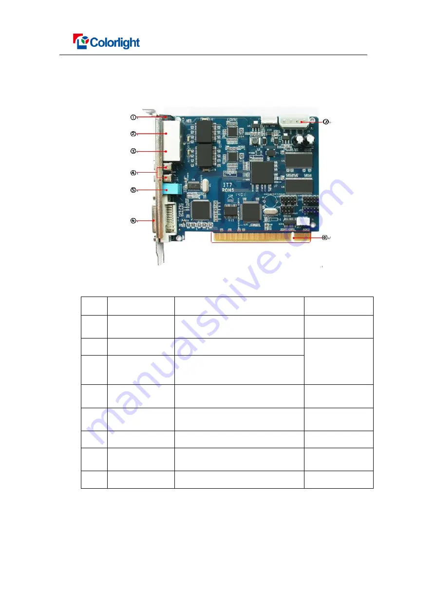
Interface functions
NO.
Interface
functions
Noted
1
indicator light
Indicates the power supply and
signal transmission state
Red for power
,
green for signal
2
Output port A
RJ45
,
connect to the receiver card The control area
of port A and B
can be
separately set
3
Output port B
RJ45
,
connect to the receiver card
4
USB 2.0
For iT7 and PC communication or
iT7 cascade
5
Audio input
transmit the audio signal to the
multifunction card
Multifunction card
needed
6
DVI input
DVI signal input
7
Power supply
DC power supply interface
(DC 3.8-12V)
8
PCI slots
Used for power supply
Only one be used
2
、
Indicator Light functions
Red: ON for power available
Green: ON/OFF quick flash indicates that the data signal transmission is normal.


