background image


Page 

22

 of 

36


SubliXpress 

Follow these steps to perform step calibration: 

Step 1:

 Select the desired pass from the list and click on the 

Print

 button (Refer to Fig 29). 

Step 2:

 Feed the correction value in the 

Revise

 field (the correction value up to two decimal paces) 

(Refer to Fig 29). 

Step 3:

 Click on the 

=>

 icon (Refer to Fig 29) on the Step Calibration window. The correction value 

result will be reflected in the 

Step

 field (Refer to Fig 29). The same step value will also be displayed in 

the 

Steps

 field on the 

Quick Access Toolbar


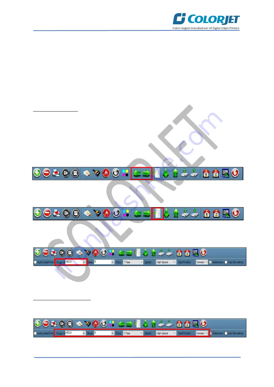
Setting Print Origin


Print origin sets the print starting point with the left limit switch as the reference point. It can be set 
by two ways; moving and positioning the carriage and typing the offset value directly in the given 
field.  

Follow these steps to change the print origin: 

Step 1

Move

 the carriage at the position from where you want to start the printing by 

clicking

 on 

the left and right buttons on the 

Quick Access Toolbar

, as shown below: 

Fig 30: Adjusting the Carriage Position 

Step 2

: After positioning the carriage, 

click

 on the 

Set print origin

 icon on the 

Quick Access Toolbar

as shown below: 

Fig 31: Selecting the Set Print Origin Option 

On clicking the 

Set print origin

 icon, the current position of the carriage gets updated in the 

Origin X


text box, as shown below: 

Fig 32: Displaying the Origin Value 

Now, the printing origin gets set. Additionally, you can also enter the print origin value manually in 
the Origin X field under the Print Parameter section. 

Setting Print Parameters 

Using  the  Printer  Manager,  you  can  manually  change  print  preferences  as  per  the  printing 
requirements such as print origin, printing speed, no of steps, and more as shown below: 

Fig 33: Setting Printing Parameters 


Summary of Contents for SubliXpress

Page 1: ......

Page 2: ...thout anyone else assistance The information provided in this document ensures its uniqueness and language quality For safe and proper use of the product please read this manual carefully and follow a...

Page 3: ...inting 13 Switch ON Procedure 13 Loading Media 13 Setting Z Height 14 Ink Supply System and Ink Filling 15 Ink Filling 16 7 Printing 17 Nozzle Testing 17 Print Head Calibration 18 Opening the Calibrat...

Page 4: ...ce 32 Print Head Maintenance 32 Head Plate Maintenance 32 11 Troubleshooting Guide 33 Printer Not Initializing 33 Printer Manager Not Showing READY 33 Print Stops in Between Printing 33 Print Margin i...

Page 5: ...es of users 2 Printer Specifications Table 1 The System Specifications of the SubliXpress SubliXpress Printing Technology Drop on demand Piezo Electric Inkjet No of Print Heads 2 and 4 Print Heads Typ...

Page 6: ...View of the machine is shown as below Fig 1 Displaying the Front View of the Machine Table 2 Different Parts of the Machine 1 Carriage Unit 2 Front Glass Door 3 Console 4 Control Panel 5 Guiding Roll...

Page 7: ...Show whether the machine is ON or OFF Bed Vacuum Switch ON OFF the bed vacuum Pre Heater Set pre heater temperature Back View The Back View of the machine is shown in the image below Fig 3 Displaying...

Page 8: ...Job Print Job Pause or resume Abort job Check nozzle Auto clean Move left Move right Set print origin Move forward Move backward Move carriage to origin and Edit job are available as buttons on the Q...

Page 9: ...created for further references Load Using this option you can load the previous saved machine s settings Save To Printer When you clicked on this option all the current settings get saved in the Main...

Page 10: ...Page 9 of 36 SubliXpress The Setting window with the Printer tab is shown in the below image Fig 7 Displaying the Setting Window The Move tab is shown in the image below Fig 8 Displaying the Move Tab...

Page 11: ...Page 10 of 36 SubliXpress The Preference Tab is shown in the image below Fig 9 Displaying the Preference Tab The Calibration tab is shown in the image below Fig 10 Displaying the Calibration Wizard...

Page 12: ...Page 11 of 36 SubliXpress The Multilayer print tab is shown in the image below Fig 11 Displaying the Multilayer print The Service tab is shown in the image below Fig 12 Displaying the Service Tab...

Page 13: ...eck Nozzle Check and more For more details please read the Calibration Wizard section carefully HW Setting This option enables to select the encoder type of the printer as per the compatibility either...

Page 14: ...wing all the steps mentioned in the Loading Media section Step 6 Finally perform purging and then nozzle test Now the printer is ready for printing Loading Media Follow these steps to load media Step...

Page 15: ...Z height using the Z Move section as shown below Fig 16 Setting the Z Height Description of different options of the Z Move section Z Max Len Refers to the Z maximum height Head to Paper Refers to th...

Page 16: ...t sensors are equipped in the sub ink tanks to control the supply of inks in tanks Overflow in sub ink tanks will pause the supply of inks and also software alerts the same The Ink Supply System is ex...

Page 17: ...olor stickers as shown below Fig 18 The Main Ink Tanks Note Main tanks are equipped with ink level sensor which beeps once the ink level goes down Now pumps start working and ink start moving in the i...

Page 18: ...an compromise the print quality by forming discolored horizontal streaks or bands The good and bad nozzle test results are shown in the image below Fig 20 Displaying the Good and Bad Nozzle Test Resul...

Page 19: ...on one by one in details Note Mechanical checks are performed by service engineer thus these checks and their description are not included in user manual Opening the Calibration Wizard Print Heads sho...

Page 20: ...right alignment and corrects it by adding or subtracting the correction value from the default set value It has to be performed for each print mode whichever is required Let s discuss each type of ho...

Page 21: ...is performed to achieve dot placement accuracy of all colors Black Cyan and Yellow with respect to Magenta during the carriage s left to right print sweep Similarly Right to Left calibration is used t...

Page 22: ...Step size needs to be adjusted for multiple factors like thickness and roughness of the print media etc Step calibration should be used to fine adjust the step size and has to be done for each desired...

Page 23: ...w these steps to change the print origin Step 1 Move the carriage at the position from where you want to start the printing by clicking on the left and right buttons on the Quick Access Toolbar as sho...

Page 24: ...Medium Speed Set the Y printing speed viz Standard Speed and Low Adding Jobs There are two ways to add jobs in the Job List area viz the Add Job button and right click on the Job List area Let s discu...

Page 25: ...er of passes can be viewed in the Job Information area User can also add a job simply by right clicking on the Job List area and selecting the Add Job option from the context menu as shown below Fig 3...

Page 26: ...h the list of options viz Clip Reverse Print and Tile Step 4 Select the desired checkbox in front of the Clip Reverse Print and Tile options On clicking to any option its related parameters get appear...

Page 27: ...ge Now you can print an image on the selected media simply by clicking on the Print Job button available on the Quick Access Toolbar as shown below Fig 40 Issuing the Print Job Command After issuing t...

Page 28: ...o options viz Time Password and Language Password The Time Password helps in setting the running time of the printer On the other hand the Language Password helps in changing the operational language...

Page 29: ...After feeding the passwords click on the Set button in front of both the options Refer to Fig 44 Step 4 Click on the Exit button to close the Password window Refer to Fig 44 Note The length of the pas...

Page 30: ...om the machine Step 4 Clean the Capping Station area and check the water in the Capping tray Step 5 Click on the Auto Capping icon to engage capping station with the head plate using the Printer Manag...

Page 31: ...g option is available to clean the head surface area The Auto Wiping option is shown in the image below Fig 46 Displaying the Auto Wiping Option On clicking the Auto Wiping icon the Manual Clean Form...

Page 32: ...urging Head purging refers to the method in which heads are cleaned by forcing pressurized ink though the nozzles The Head Purging button of each color is shown in the image below Fig 49 Purging Inks...

Page 33: ...zzle test daily 2 3 times before printing to monitor the blockage in the head nozzles Avoid head damage due to media and Print Head confliction Color Bar should be ON Avoid ink spilling on the Print H...

Page 34: ...Pulley or belt is slipping Ripped file is having error Media is finished Print Margin is Shifting or Junk Printing Encoder scale is having ink stains Encoder sensor is not clean Pulley or belt is sli...

Page 35: ...required Check if any air lock or no ink in the head pipes Check the ink and air pipe for any cuts or loose connection Ink Not Supply Damaged float sensitivity Power board fault Float power line failu...

Page 36: ......

Page 37: ...For Any Query Please Contact Us www colorjetgroup com Call us on 91 120 4548195 Email on info colorjetgroup com For Ink Enquiry sales colorjetgroup com For Support support colorjetgroup com...

Reviews: