background image

20

Starting

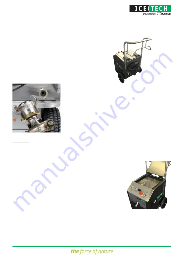
When the machine has been set up as described above (points 1-5), the following pro- 

cedure shall be followed before the cleaning process has begun:

4.  Connect the main power supply.

5.  Connect the compressed air supply.

6.  Check carefully to ensure that the dosing unit is 

dry and clean at the hopper outlet.

Summary of Contents for IceTech Evolution Line Xcel 6

Page 1: ...Manual ENG EL MANUAL Rev A...

Page 2: ...2 IceTech A S Industrivej 62 DK 6740 Bramming Copyright 2016 by IceTech A S All rights reserved...

Page 3: ...3 Date Rev Document Description Affected Pages August 16 2016 A SOP All Revision History...

Page 4: ...l Qualifications 7 Precautions during Blasting 8 Static Electricity 8 PACEMAKER Precautions 8 Explosive Hazard 8 Danger of Thrown Loose Objects 9 Noise 9 Dust 9 Protective Clothing 9 CO2 Detector 10 C...

Page 5: ...CE 27 Daily before Starting the Machine 27 After 100 Hours of Operation 27 After 500 Hours of Operation 27 REPAIR AND WARRANTY 28 Repair 28 Terms of Warranty 28 NOZZLE SELECTION AND AIR CONSUMPTION 29...

Page 6: ...ods DRY ICE BLASTING How It Operates Dry Ice Pellets The dry ice blasting machine uses small CO2 particles as the blasting medium called dry ice pellets CO2 the chemical symbol for carbon dioxide In a...

Page 7: ...ns which must be followed whilestarting operatingandmaintainingthedryiceblastingmachine Itisimportant that the manual is kept so the operator always knows its exact location It is also important the o...

Page 8: ...to be cleaned are adequately earthed grounded and that this earthing grounding remains stable throughout the whole cleaning process The dry ice blasting machine is earthed grounded from machine cabin...

Page 9: ...he high air velocities in the gun nozzle during dry ice blasting the level of noise in the area where the operator works may exceed the maximum permissible level The owner is responsible for keeping h...

Page 10: ...CO2 especially if the blasting process takes place in small or partly closed rooms In such conditions there is a risk of the oxygen content of inhaled air being replaced by CO2 Therefore it is essent...

Page 11: ...11 MACHINE ILLUSTRATIONS 1 Control panel 2 Signal cable connection 3 Connection for blasting hose 4 Top lid for the hopper...

Page 12: ...12 1 Dry ice hopper 2 Blasting hose connection 3 Electrical box 4 Pneumatic vibrator 5 Dosing system...

Page 13: ...13 1 Power cable 2 Air filtration unit with regulation 3 Exhaust pipe 4 Flanged connection 5 Transformer...

Page 14: ...rtant When lifting with a forklift truck make sure that the forks are inserted all the way under the machine frame itself When using a crane for lifting a yoke with straps under the cabinet frame must...

Page 15: ...15 LABELS ON THE MACHINE Identification Plate Warning Signs Label...

Page 16: ...16 CONTROL PANEL 1 Supply air pressure 2 Blasting pressure 3 Blasting pressure control 4 Reset button 5 On Off button 6 Dry ice consumption control 7 Emergency Stop...

Page 17: ...machine 2 Signal cable for connection on front of the dry ice blasting machine 3 Signal cable for connection to the blasting gun 4 Hose coupling for connection to the blasting gun The IceTech blastin...

Page 18: ...Safety switch 3 Two step trigger 4 Signal cable 5 Standard Round Nozzle interchangeable 6 Nozzle adapter Technical Specifications Dim mm inch without nozzle Length 270 10 63 Width 60 2 36 Height 225...

Page 19: ...wheel brakes are applied 2 Plug the blasting hose couplings into the socket on the front of the machine and the blasting gun respectively Checktomakesurethehosecouplings are correctly connected 3 Con...

Page 20: ...ed above points 1 5 the following pro cedure shall be followed before the cleaning process has begun 4 Connect the main power supply 5 Connect the compressed air supply 6 Check carefully to ensure tha...

Page 21: ...he emergency stop button is pulled out 10 Turn the machine ON press the ON OFF button and press the Reset button to activate the emergency relay 8 Fasten the earth connection wire in the butter y nut...

Page 22: ...gun for a few seconds to allow air to flow through the system This checks for moisture in the airstream and proper operation of the dosing disc vibrator and regulator 12 Fill dry ice pellets into the...

Page 23: ...23 13 Adjust the dry ice consumption kg hr lbs min and the blasting pressure bar psi the value is shown on the pressure gauge 14 Start dry ice blasting...

Page 24: ...Disconnect the main power supply Bleed the pressure from the air supply lline Disconnect the compressed air supply It is recommended to disconnect the blasting hose Avoid kinking the blasting hose whe...

Page 25: ...used the operator risks serious injury from being hit by dry ice pellets Any sign of inflation means that the inner hose is in some way defective NOTE If that fault occurs stop the machine IMMEDIATELY...

Page 26: ...nnection supplies the machine with LN PE L N respecting the live phase L neutral N and ground PE connections The machine voltage is specified on the rating plate The control circuits use 24 V DC OFF B...

Page 27: ...continues to comply with the safety regulations after repair After 100 Hours of Operation 1 Examine connections for wear and tear or other damage Tighten up or replace them as necessary 2 Check the do...

Page 28: ...st always be made either by an IceTech technician or by the owner s qualified personnel who have been trained by IceTech in the repair and maintenance of IceTech dry ice blasting machines and accessor...

Page 29: ...e size of nozzle which will provide the desired air velocity using the available compressor capacity Choosing the right nozzle size and type will optimize not only the cleaning effect but also the dry...

Page 30: ...0 3 8 4 6 5 3 6 1 6 9 7 7 8 4 9 4 10 1 10 8 11 7 12 1 13 10 2 8 3 7 4 7 5 7 6 6 7 6 8 5 9 6 10 4 11 3 12 4 13 4 14 3 15 3 16 Air consumption in Nm3 min at the pressures indicated bar nozzle diameter P...

Page 31: ...Blasting Pressure bar psi min 2 max 10 min 29 max 145 Air Consumption Nm3 min cfm depending on nozzle combination 0 7 3 7 29 131 Compressed Air Connection 3 4 Claw Coupling Air Quality According to IS...

Page 32: ...re is regulated above 0 psi bar Check signal cable connections For further support call Customer Service 1 800 777 9101 USA 32 0 1353 9659 Europe Dosing unit is not working ice is not flowing Check Ic...

Page 33: ...ards printed circuits etc Light weight aluminium Max Ice Min Air Max Ice Min Air Max Ice Min Air Max Ice Min Air kg h kg h kg h kg h Splitternet mm 1 5 2 2 5 3 5 20 4 25 4 30 4 35 4 61 25 4 30 4 35 3...

Page 34: ...58 kg h 87 kg h 127 kg h 31 kg h 6 4 bar 5 V 65 kg h 97 5 kg h 142 5 kg h 35 kg h 8 0 bar 6 V 72 kg h 108 kg h 158 kg h 39 kg h 9 6 bar 7 V 79 kg h 118 5 kg h 173 5 kg h 43 kg h 11 2 bar 8 V 86 kg h 1...

Page 35: ...35 EC Declaration ICE TECH A S INDUSTRIVEJ 62 DK 6740 BRAMMING TEL 45 76 56 15 00 FAX 45 76 15 09 EC DECLARATION OF CONFORMITY FOR MACHINERY...

Page 36: ...36 IceTech A S Industrivej 62 DK 6740 Bramming Copyright 2016 by IceTech A S All rights reserved...

Reviews: