51
4. DISASSEMBLING AND SERVICING
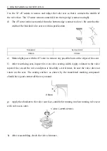
VALVE FACE
CUTTER
HOLDER
IN.
:
32
°
EX.
:
32
°
IN.
:
45
°
EX.
:
45
°
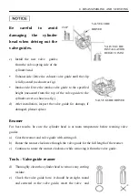
the guide may have been bent during installation. Replace the valve guide if it is bent or
damaged.
f)
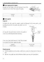
Check the valve stem-to-guide clearance.
g)
The valve stem-to-guide clearance
:
The vale guide bore detract the valve stem outside diameter to get the clearance between
the valve guide and valve stem.
h)
If the clearance is over the service limit, judge a new guide if it can make the clearance
Conforming to service limit, if conforming to replace the guide and ream the guide,
refinish the valve when replacing the valve guide.
④
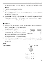
Valve seat
a)
Thoroughly clean the combustion chambers and valve seats to remove carbon deposits.
Apply a light coat of red lead powder or erasable
color painting to the valve faces.
b)
Insert the valves, and then press the valve Several
times forcefully. Be sure the valve does not rotate
on the seat. The transferred marking compound
will show any area of the seat that is not concentric.
c)
Using 45°cutter, remove enough material to produce a smooth and concentric seat. Turn
cutter clockwise, never counterclockwise. Continue to turn the cutter as you lift it from
the valve seat.
Tool
Valve seat cutter
Summary of Contents for Y173V
Page 4: ......
Page 8: ...2 DIMENSION AND TORQUE 4 2 DIMENSION AND TORQUE 2 1 Dimension ...
Page 48: ...46 4 DISASSEMBLING AND SERVICING INTAKE VALVE Reassembly ...
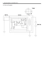
Page 64: ...4 DISASSEMBLING AND SERVICING 4 5 Electric Diagrams ...
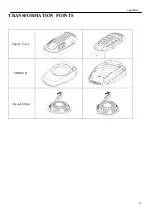
Page 65: ...61 appendix TRANSFORMATION POINTS Engine Cover SHROUD Recoil Starter ...
Page 66: ......

