background image

Contents

Features

 .........................................................................................................1

The CB Story

 .................................................................................................A1

FCC Regulations, FCC Warnings & Included Accessories

Controls & Indicators

 ................................................................................A2

Our Thanks to You

 .....................................................................................A3

Customer Support

Installation

Location & Mounting/Connection ..................................................2

Antennas

CB Antenna & Marine Installation ...................................................6

Ignition Noise Interference

....................................................................7

Operating Your 25 LX

Turning On Your CB .............................................................................. 8

Setting Channel Selector .................................................................... 9

To Receive ................................................................................................ 10

Selecting a Channel .............................................................................. 10

S-Meter ...................................................................................................... 11

To Transmit .............................................................................................. 12  

Setting Dynamike® ............................................................................... 13

Menu Mode ............................................................................................. 14

Setting the Clock ................................................................................... 15  

Setting the Alarm .................................................................................. 15

Setting the Count Down Timer ........................................................ 16  

Setting Display Color Mode ............................................................... 17

Setting Brightness Mode .................................................................... 18 

Setting Contrast Mode ........................................................................ 18

Key Tones Mode .................................................................................... 19  

Radio Check Mode ................................................................................ 19

Software Version/Factory Settings ................................................. 20

NB/Off (Noise Blanker/Automatic ................................................... 21

Noise Limiter Switch)

RF Gain Control ...................................................................................... 21

Program Memory Channels ............................................................... 22

Scan CB Channels .................................................................................. 23

Scan/Memory Scan ............................................................................... 23

Scan Memory Channels ...................................................................... 23

Dimmer Control ..................................................................................... 23

Setting Squelch ...................................................................................... 24

S/RF Meter ................................................................................................ 26

External Speaker .................................................................................... 27

PA (Public Address) ............................................................................... 28

Home And Office Set-Up .................................................................... 30

Temporary Mobile Set-Up .................................................................. 31

How Your CB Can Serve You

 ................................................................. 32

A Few Rules You Should Know ........................................................32

Channel 9 Emergency Messages .....................................................32

CB 10 Codes .............................................................................................34

Frequency Ranges

 .....................................................................................36

25 LX Specifications

 ..................................................................................37

Warranty Information

 ..............................................................................38

Optional Accessories

 ................................................................................39

If You Need Service/Trademark Info

 ................................Back Cover

Features of This Product
•   Selectable 4-Color LCD Display
•  40 CB Radio Channels
•  40 Channel Scan
•  Memory Channels
•  Channel Frequency Read-Out
•  Radio Check Diagnostic
•  Clock/Timer/Alarm
•   Heavy-Duty Dynamic  

Microphone 

•  Full 4 Watts AM RF Power Output
•  Instant Channel 19 and 9
•   Front Panel 4-Pin Microphone 

Connector

•   Switchable Noise Blanker
•   Adjustable Dynamike Boost
•  Tactile Controls
•  9 Ft Mic Cord
•  Programmable Dimmer Control
•  RF Gain

1

How to Use Your Cobra 25 LX

25LX_MANL.indd   1

11/15/11   9:42 AM

For Sales Information Please Contact 


RoadTrucker Inc (www.RoadTrucker.com) 

8312 Sidbury Rd. 

Wilmington, NC 28411 

(800) 507-0482 / (910) 686-4281

Summary of Contents for 25 LX

Page 1: ...nels 23 Dimmer Control 23 Setting Squelch 24 S RF Meter 26 External Speaker 27 PA Public Address 28 Home And Office Set Up 30 Temporary Mobile Set Up 31 How Your CB Can Serve You 32 A Few Rules You Should Know 32 Channel 9 Emergency Messages 32 CB 10 Codes 34 Frequency Ranges 36 25 LX Specifications 37 Warranty Information 38 Optional Accessories 39 If You Need Service Trademark Info Back Cover Fe...

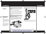
Page 2: ...er The transceiver is usually mounted to the under side of the dash with the microphone bracket beside it Note The transceiver is held in the universal mounting bracket by two thumbscrews which allow for adjustment at a convenient angle The bracket includes two self tapping screws and star wash ers The mounting must be mechanically strong conve niently located continued Drill the holes and secure ...

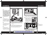
Page 3: ... cord to an accessory 12 volt fuse Connect the black lead to the negative side of the vehicle This is usually the chassis Any convenient location with a good electrical contact remove paint may be used 4 5 Plug power cable into back of unit marked Power Be sure to observe polarity markings Mount the microphone bracket on either side of the unit driver s left using two screws sup plied Bracket shou...

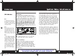
Page 4: ...For models with Weather Feature WX a Dual Band Center Load Base Load antenna is recommended Consult your Cobra dealer for further details or call 773 889 3087 and speak to a Cobra representative Marine Installation The transceiver will not operate at maximum efficiency in a boat without a ground plate unless it has a steel hull Before attempting installation consult your dealer for information reg...

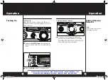
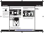
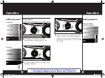
Page 5: ...ng level Select one of forty channels and adjust volume The selected channel 1 through 40 will be indicated by the readout directly above the channel selector knob 3 SIG 30dB 1 1 2 3 4 TX PWR 3 5 7 9 MEM NB TX RX VOL SQ OFF DYNAMIKE MIN RF GAIN MIN MAX M ENU PUSH ENTER SCAN M SCAN DIM ESC CB PA NB CH9 19 Note Press CB PA to select CB or PA public address mode SIG 30dB 1 1 2 3 4 TX PWR 3 5 7 9 MEM ...

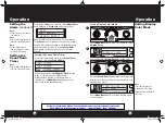
Page 6: ...2 3 4 TX PWR 3 5 7 9 MEM NB TX RX VOL SQ OFF DYNAMIKE MIN RF GAIN MIN MAX M ENU PUSH ENTER SCAN M SCAN DIM ESC CB PA NB CH9 19 SIG 30dB 1 1 2 3 4 TX PWR 3 5 7 9 MEM NB TX RX VOL SQ OFF DYNAMIKE MIN RF GAIN MIN MAX M ENU PUSH ENTER SCAN M SCAN DIM ESC CB PA NB CH9 19 SIG 30dB 1 1 2 3 4 TX PWR 3 5 7 9 MEM NB TX RX VOL SQ OFF DYNAMIKE MIN RF GAIN MIN MAX M ENU PUSH ENTER SCAN DIM CB PA NB CH9 19 25LX...

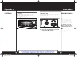
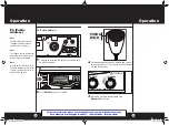
Page 7: ... volume is available Dynamike may have to be reduced in some conditions 2 Transmit Push and hold mic button to transmit Transmitter is now activated When transmit ting hold the microphone two inches from your mouth and speak in a clear normal voice Release to receive SIG 30dB 1 1 2 3 4 TX PWR 3 5 7 9 MEM NB TX RX VOL SQ OFF DYNAMIKE MIN RF GAIN MIN MAX M ENU PUSH ENTER SCAN M SCAN DIM ESC CB PA NB...

Page 8: ...U SH EN TER SIG RF 30dB 1 1 5 2 3 CAL 3 5 7 9 SWR TX RX NB ANL MEM WX ANL S RF SWR CAL CH 9 19 CB WX DIM SCAN PA EXIT SIG 30dB 1 1 2 3 4 TX PWR 3 5 7 9 MEM NB TX RX VOL SQ OFF DYNAMIKE MIN RF GAIN MIN MAX M ENU PUSH ENTER SCAN M SCAN DIM ESC CB PA NB CH9 19 SET CLOCK ALARM CLOCK SET COUNT DOWN DISPLAY COLOR BRIGHTNESS CONTRAST Level 1 Level 2 SWR CAL NB ANL VOL SQ DYNAMIKE RF GAIN DELTA TUNE T BAC...

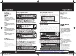
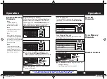
Page 9: ...ts Setting the Count Down Timer Note Press Dim Escape button to return to CB standby mode Setting Display Color Mode Note Select EXIT to return to main menu Press Dim Escape button to return to CB mode Setting Display Color Mode Press Menu Enter knob and scroll down to select Display Color Press and release Menu Enter to set the color Rotating Menu Enter knob clockwise changes the display color fr...

Page 10: ...ode Radio Check Mode Allows testing of important radio functions Test 1 Battery Level Confirms that battery voltage level is between 10 8 V to 15 8 V If in that range it is PASS Outside of that range either FAIL LOW or FAIL HIGH will be displayed Press Menu Enter knob to advance to next test Note Press Dim Escape button to return to CB standby mode If 10 seconds pass or if Enter button pressed uni...

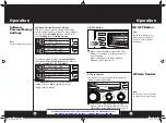
Page 11: ...iltration When switched to OFF mode all noise filtration will be turned off NB OFF Button RF Gain Control RF Gain Control The RF Gain is used to optimize reception in strong or weak signal areas Note The RF Gain is used to optimize reception in weak signal areas Note The RF noise blanker is very effective in reducing repeti tive noises such as ignition interference Rotate the RF Gain knob counterc...

Page 12: ...e a channel from memory go to the unwanted memory channel then press and hold the scan button until the MEM icon turns off Dimmer Control Dimmer Control 1 Press Dim Esc button to toggle between day and night settings See setting instructions on page 20 SIG 30dB 1 1 2 3 4 TX PWR 3 5 7 9 MEM TX RX VOL SQ OFF DYNAMIKE MIN RF GAIN MIN MAX M ENU PUSH ENTER SCAN M SCAN DIM ESC CB PA NB CH9 19 Scan CB Ch...

Page 13: ...IN MIN MAX M ENU PUSH ENTER SCAN M SCAN DIM ESC CB PA NB CH9 19 SIG 30dB 1 1 2 3 4 TX PWR 3 5 7 9 MEM NB TX RX VOL SQ OFF DYNAMIKE MIN RF GAIN MIN MAX M ENU PUSH ENTER SCAN M SCAN DIM ESC CB PA NB CH9 19 To achieve the Desired Squelch Setting DSS turn the Squelch control counterclockwise until you hear noise Now turn the control clockwise just until the noise stops This is the DSS setting 3 NOISE ...

Page 14: ...ternal speak er is plugged in the internal speaker is automatically discon nected See accessory page 43 Note Cobra external speakers are rated at 10 watts Connect an external speaker to the external speaker jack on the rear panel 1 26 SIG 30dB 1 1 2 3 4 TX PWR 3 5 7 9 MEM NB TX RX VOL SQ OFF DYNAMIKE MIN RF GAIN MIN MAX M ENU PUSH ENTER SCAN M SCAN DIM ESC CB PA NB CH9 19 25LX_MANL indd 26 27 11 1...

Page 15: ... from the microphone to prevent acoustic feedback Note Activity on the CB channel will be heard through the PA speak er Adjust Volume Control to a normal listening level 1 2 3 4 PUSH HOLD SIG 30dB 1 1 2 3 4 TX PWR 3 5 7 9 MEM NB TX RX VOL SQ OFF DYNAMIKE MIN RF GAIN MIN MAX M ENU PUSH ENTER SCAN M SCAN DIM ESC CB PA NB CH9 19 SIG 30dB 1 1 2 3 4 TX PWR 3 5 7 9 MEM NB TX RX VOL SQ OFF DYNAMIKE MIN R...

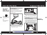
Page 16: ...a 13 2 volt DC Power Pack rated at a minimum of 2 amps and a properly installed base station antenna Warning Do not attempt to operate this transceiver by connecting it directly to 120V AC Note For further information call Cobra Customer Service 1 773 889 3087 1 Connect properly installed and matched base station antenna Simply connect the red and black leads of the transceiver to the correspondin...

Page 17: ...t I njuries Number Type Trapped P roblem Give details and help needed Transmit CLIP repeatedly so any monitor can assist Channel 9 Emergency Messages Note If no response on channel 9 try channels 19 or 14 Warn of traffic problems Provide weather and road data Provide help in event of an emergency Provide direct contact with home or office Assist police by reporting erratic drivers Get local inform...

Page 18: ...pleted all units secure 10 200 Police needed at CB 10 Codes Citizen Bands have adopted the 10 CODES for standard questions and answers These codes provide quick and easy communication especially in noisy areas Following are some of the more common codes and meanings Code Meaning 10 1 Receiving poorly 10 2 Receiving well 10 3 Stop transmitting 10 4 OK message received 10 5 Relay message 10 6 Busy s...

Page 19: ...Audio Output Power 4 watts Frequency Response 300 to 3000 Hz Distortion Less than 7 3 watts 1000 Hz Built in Speaker 8 ohms 5w External Speaker Not supplied 8 ohms disables internal speaker when connected PA SYSTEM Power Output 4 watts into external speaker External Speaker for PA 8 ohms 4 Watts min Not Supplied the PA speaker also monitors the receiver separate jack provided SPECIFICATIONS SUBJEC...

Page 20: ...bility and fitness for a particular purpose are limited in duration to the length of this warranty Cobra shall not be liable for any incidental consequen tial or other damages including without limitation damages resulting from loss of use or cost of installation Some states do not allow limitations on how long an implied warranty lasts and or do not allow the exclusion or limitation of incidental...

Page 21: ...riday Central Time Technical assistance is also available on line in the Frequently Asked Questions FAQ section at www cobraelec com or by e mail to productinfo cobra com If you think you need service call 1 773 889 3087 If your product should require factory service please call Cobra first before sending your unit in This will ensure the fastest turn around time on your repair You may be asked to...

Page 22: ...PWR 3 5 7 9 MEM NB TX RX VOL SQ OFF DYNAMIKE MIN RF GAIN MIN MAX M ENU PUSH ENTER SCAN M SCAN DIM ESC CB PA NB CH9 19 6 9 12 11 15 NOTE This device complies with part 15 of the FCC Rules Operation is subject to the following two 2 conditions 1 This device may not cause harmful interference and 2 This device must accept any interference received including interference that may cause undesired opera...

Reviews: