Removal and replacement of ADU modules
98-133966-G1
Chapter 8: Service & maintenance
8-57
8888
Service & maintenance
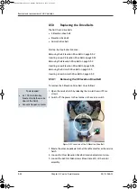
8. Loosen the 4x4 mm Allen screws (thread size M5) of the motor
assembly.
9. Lift the complete Cross Elevation Motor & Encoder assembly free, in
the key holes, from the pedestal and remove it.
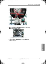
Figure 8-71: X-Elevation Motor & Encoder — belt tension/adjustment
screw
Figure 8-72: Cross Elevation motor assembly, 4 Allen screws
SAILOR900TM.book Page 57 Monday, September 16, 2013 11:01 AM
Summary of Contents for Sailor 900 VSAT
Page 2: ...98 138976 A Cover_SAILOR 900 VSAT System_407090B indd 2 15 04 2013 15 54 39 ...
Page 28: ...List of tables xxvi 98 133966 G1 SAILOR900TM book Page xxvi Monday September 16 2013 11 01 AM ...
Page 257: ...Appendices SAILOR900TM book Page 1 Monday September 16 2013 11 01 AM ...
Page 258: ...SAILOR900TM book Page 2 Monday September 16 2013 11 01 AM ...
Page 355: ...98 138976 A Cover_SAILOR 900 VSAT System_407090B indd 3 15 04 2013 15 54 40 ...


