


GR716-DS-UM, May 2019, Version 1.29
505
www.cobham.com/gaisler
GR716
51.3
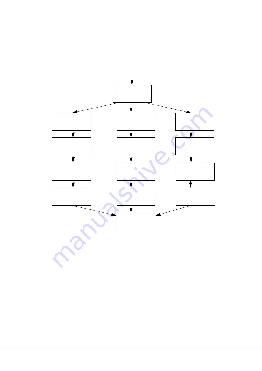
Loader description
Load sequence is the summing-up of Boot software components executing after standby mode. The
component includes enable clocks and pins, image loading and application software boot.
Figure 91.
Load sequence detailed description
For more information see Table 672.
51.4
Standby description
After processor initialization has completed the Standby mode is started if selected by the bootstrap
signals. The bootstrap configures which interface is used for the remote control. For each of the
remote access options the boot software enable interface clock and pins. See sections below for more
information about which pins are used for respective interface.
Full access is granted to the unit accessing the GR716 Microcontroller via the selected remote control
and access interface. When remote control unit upload new software to the GR716 Microcontroller
the remote unit can reset and re-start the processor via the interrupt controller unit, see chapter 40 for
more information. The remote unit needs to instruct the GR716 Microcontroller to restart and start
executing the uploaded software.
While in standby mode the processor is in power-down mode. The watchdog timer is activated during
Standby mode.
Check
Boot
Mode selected
Enable SPI
clock and pins
From Processor Module Initialization
SPIM
I2C
SRAM/PROM
Enable I2C
clock and pins
Enable SRAM
clock and pins
Configure
external memory
Configure
external memory
Configure
external memory
Boot direct or
load ASW image
Load ASW
boot image
Load redundant
load ASW image
Load redundant
load ASW image
Boot direct or
load ASW image
Load redundant
load ASW image
Go to start
(Start user SW)