background image

Setup with the web interface for PC

4-4

Chapter 4:  Setup and operation

98-144390-C

The 

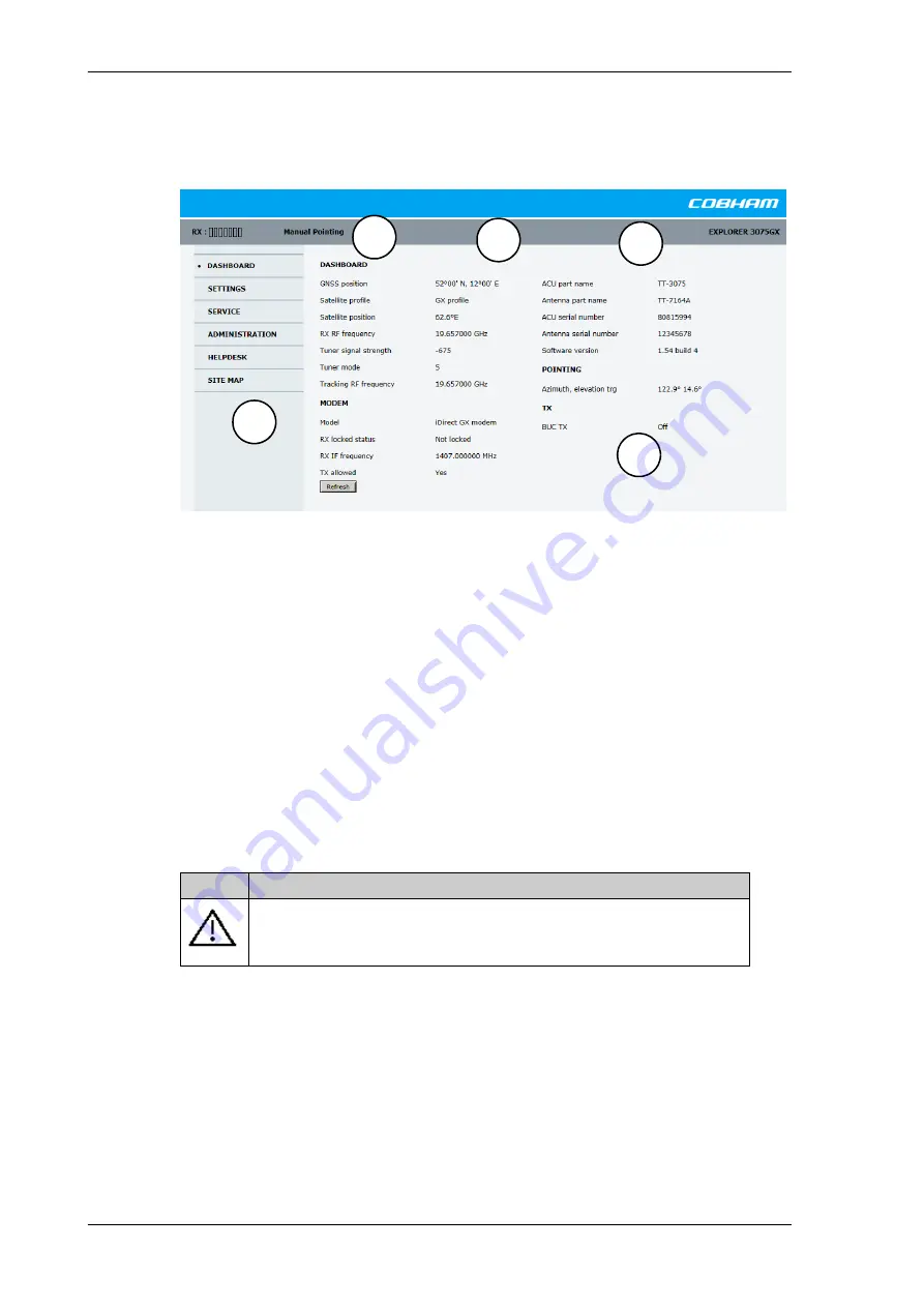
DASHBOARD

 is the first screen that is displayed. It shows the properties and status of 

the EXPLORER 3075GX.

The web interface has the following sections:

1. The navigation pane holds the main menu. Clicking an item in the menu opens a 

submenu in the navigation pane or a new page in the contents section.

2. The signal status field shows the tracking signal strength. The signal strength can vary 

during operation, depending on the current position relative to the satellite.

3. The icon bar shows icons for active events, when relevant, and the system status. 

4. The host name is shown on every page of the web interface. The host name is useful for 

identifying the system at remote login and when requesting reports from the system. 
You can change the host name, se

To configure the LAN network

 on page 4-7.

5. The contents section shows the page selected in the navigation pane. This section is 

used for viewing or changing settings, or for performing actions.

The following icon may appear in the icon bar in the web interface:

To navigate the web interface

To expand a menu

, click the menu in the navigation pane. 

To access status and settings

, click the relevant subject in the navigation pane or 

click the relevant icon in the icon bar. The status or settings are displayed in the contents 
section.

Figure 4-4: Web interface: DASHBOARD

Icon

Explanation

An event is active. Click the icon to see a list of active events. For 
explanations of the event messages, see 

List of events

 on page B-2. Note 

that this icon will remain in the icon bar as long as the event is active.

Table 4-1: Web interface: Event icon

1

2

3

5

4

Summary of Contents for EXPLORER 3075GX

Page 1: ...EXPLORER 3075GX Manual Deploy Fly Away System for Inmarsat GX User installation manual...

Page 2: ...rsion shall be the governing text Thrane Thrane A S is trading as Cobham SATCOM Copyright 2018 Thrane Thrane A S All rights reserved Trademark acknowledgements Inmarsat is a registered trademark of th...

Page 3: ...upply The voltage range for the EXPLORER 3075GX is 100 240 VAC nominal 4 A 50 60 Hz Use the original power cable delivered with the equipment and make sure to apply safety ground to the terminal Do no...

Page 4: ...accordance with the instructions may cause harmful interference to radio communications However there is no guarantee that interference will not occur in a particular installation If this equipment do...

Page 5: ...WLAN 2 6 2 2 7 Power supply 2 6 Chapter 3 Assembly start up 3 1 What s in the box 3 1 3 1 1 To unpack 3 1 3 1 2 Initial inspection 3 2 3 2 To assemble the EXPLORER 3075GX 3 2 3 2 1 Prerequisites 3 2...

Page 6: ...5 1 6 LNB data update 5 7 5 1 7 Proxy server settings in your browser 5 8 5 2 Software update 5 9 5 2 1 Prerequisites 5 9 5 2 2 Software update procedure 5 9 5 3 Status signalling with LEDs and statu...

Page 7: ...bserve all safety requirements listed in the beginning of this manual and install the system according to the guidelines in this manual 1 1 2 Software version This manual is intended for EXPLORER 3075...

Page 8: ...gives information that is important to the user e g to make the system work properly This text does not concern damage on equipment or personal safety All personnel who operate equipment or do mainten...

Page 9: ...s terminals are easy to install set up and commission by a non specialist technician The system has the following major components 1 2 axis manual control antenna positioner with Inter Facility Link a...

Page 10: ...e The EXPLORER 3075GX is a unique GX antenna system operating in the K Ka band 19 2 to 30 GHz It is used with the Global Xpress service from Inmarsat delivering consistent high performance download sp...

Page 11: ...ependent axes to allow for precise antenna pointing The antenna positioner can stay outside in rainy weather Manual controls The manual control panel includes Azimuth and elevation adjustment controls...

Page 12: ...nd disassembly of the RF assembly from the tripod 2 2 3 Reflector The 75 cm reflector consists of four interchangeable panels and a center hub The panels are made entirely of composite with the except...

Page 13: ...8 for a list of menus The menus show how the system has been configured The three LED light indicators are described in LEDs on the keypad of the EXPLORER 3075GX on page 5 12 You can see warnings erro...

Page 14: ...e connectors LAN2 to LAN4 for user PCs for Internet etc configured by the GX modem The EXPLORER 3075GX has a WLAN module Access to one of the LAN ports using WLAN must be set up in the web interface s...

Page 15: ...mble and pack the antenna 3 1 What s in the box 3 1 1 To unpack Two transit cases contain the EXPLORER 3075GX antenna system Case with RF assembly and electronics enclosure left Case with tripod anten...

Page 16: ...not work properly notify your dealer 3 2 To assemble the EXPLORER 3075GX 3 2 1 Prerequisites Wind speed considerations The antenna is designed to operate under wind speeds of 48 km h 30 mph gusting up...

Page 17: ...marked circle Make sure the legs are as widely spread as possible to support the RF assembly and the reflector petals Fasten each leg by turning the black locking lever 3 In high wind conditions you...

Page 18: ...ssembly 9 Insert the two bottom panels and latch them along the edge of each panel to carefully secure the reflector panels into place 10 Re secure the locking mechanism for each panel on the reflecto...

Page 19: ...here are four RJ 45 ports for making IP data connections LAN cable type Use shielded LAN cable LAN connector on the left hand side LAN1 for system control via the web interface Three connectors LAN2 t...

Page 20: ...XPLORER 3075GX goes through an initialization procedure 2 Wait until the display of the electronics enclosure shows DEPLOYED IDLE first power on after factory reset or MANUAL POINTING The Power and Fa...

Page 21: ...heavy when mounted on the tripod and the elevation knob may be hard to turn If you have trouble turning the knob gently pull the RF package towards you while turning the knob 9 Fine tune the azimuth...

Page 22: ...LAN port 1 and continue at Connection to the web interface on page 4 1 For a description of the keypad and display see section Keypad and display menus on page 4 17 3 4 To disassemble and pack the an...

Page 23: ...4 21 4 1 2 Connection to the web interface To connect to the web interface do as follows 1 Switch on the EXPLORER 3075GX system Wait until the LEDs on the front plate show that the system is ready to...

Page 24: ...INISTRATION User login and locate the section Change Login 6 If needed type in the new password minimum 8 characters and click Change No old password is required After the 1 hour window or a restart t...

Page 25: ...inting on page 3 6 The antenna is fully operational when the display of the electronics enclosure shows ACQUISITION OK and the field in the upper status line of the display shows MDM NETOK Topics in t...

Page 26: ...system at remote login and when requesting reports from the system You can change the host name see To configure the LAN network on page 4 7 5 The contents section shows the page selected in the navig...

Page 27: ...y an error description Sections on the Dashboard Note You can give access to some configuration settings for users that are not administrators For information see User permissions guest login on page...

Page 28: ...d or Not locked Demodulator lock of the modem RX IF frequency Read out from the modem TX allowed Yes or no reported from the internal GX modem Table 4 3 Web interface DASHBOARD MODEM section TX Descri...

Page 29: ...d by the GX modem To configure the LAN network do as follows 1 Select SETTINGS Network 2 Make the necessary changes on this page and click Apply Important The EXPLORER 3075GX system is not designed to...

Page 30: ...t value can be displayed in the EXPLORER 3075GX display The service port has 3 modes Static default DHCP client Used when the antenna is on a local network Switched with port 5 For direct access to th...

Page 31: ...sers Disabled WLAN access point is hidden 6 Type in the SSID of your choice or accept the default SSID which is Cobham The SSID is the name of the wireless local area network It is a text with maximum...

Page 32: ...where access to the EXPLORER 3075GX is not intended and or difficult Do as follows 1 Select SETTINGS Navigation from the left navigation pane 2 Set the Heading Position Manual pointing and Fixed insta...

Page 33: ...e Administration settings require an Administration user name and password To log on as administrator do as follows 1 Open your Internet browser and enter the IP address of the EXPLORER 3075GX http 19...

Page 34: ...needed type in the new password minimum 8 characters and click Change No old password is required After the 1 hour window or a restart the administrator password is required To log off administration...

Page 35: ...ing an LNB Control Modem Locks the page SERVICE Modem for guest users This page is used to reset or power cycle the GX modem 3 Click Apply 4 1 8 Import and export of a system configuration The configu...

Page 36: ...into another EXPLORER 3075GX To load a configuration from a file do as follows 1 Select ADMINISTRATION Export import config 2 Click the button Choose File and locate and double click the configuratio...

Page 37: ...tellite profiles All added VSAT modem profiles Changes in the network setup User permissions Display brightness setting To reset to factory default settings do as follows 1 Select ADMINISTRATION Facto...

Page 38: ...Test Mode Only connection to the GX modem is the serial RS 232 interface all other connections are shut down Do not use Level 3 Default Factory Configuration CAUTION Administrators only Close this pag...

Page 39: ...to see current events 2 Current menu see The menu tree on page 4 18 3 NAV Navigational information First letter G Valid position signal received from the GNSS module or g No valid GNSS fix Second lett...

Page 40: ...ress again to move one level up If applicable confirm to store the new setting by pressing OK 4 2 3 The menu tree In the menu tree you can see how the system has been configured To enter satellite inf...

Page 41: ...ormation including modem LED status SATELLITE Current satellite information This information is selected using the web interface NETWORK Shows the IP addresses and netmasks of the LAN connectors and t...

Page 42: ...ected GX modem RX LOCK On or off information delivered by the connected GX modem NET LED Modem status Steady or flashing green yellow red OFF STAT LED TX LED RX1 LED RX2 LED PWR LED TEMP LED FAN LED T...

Page 43: ...Activate a satellite profile See status and events Access the web interface PC version To access the mobile web interface do as follows 1 Press the On Off button to power up the EXPLORER 3075GX 2 Conn...

Page 44: ...e web interface logon page and status page Description Status Shows the system status host name position heading selected satellite profile modem etc Satellites Lets you select which satellite to acti...

Page 45: ...quire a minimum amount of regular maintenance Make the following checks on a regular basis Inspect the reflector front surface for physical damage including chips and cracks Any substantial damage can...

Page 46: ...ervice and Support Cobham Satcom Service and Support Technical Downloads 5 Click Legal notice to display the licence text for the source code of the parts of the EXPLORER 3075GX software that fall und...

Page 47: ...essage and a short text describing the error Active events are cleared from the event list when the error is cleared They are moved to the section Notifications and are displayed for 24 hours All entr...

Page 48: ...ofile will be used To reset the GX modem to factory defaults use the web interface See Reset to factory default integrated GX modem on page 4 16 5 1 4 Satellite profiles and modem profiles A satellite...

Page 49: ...the settings for the satellite profile Modem profiles On the page Modem profiles you create edit or delete VSAT modem profiles The VSAT modem profile GX Modem is already set up at the factory It is us...

Page 50: ...ommissioning OTC for the modem 1 Connect a PC to LAN1 2 Enter the web interface via Firefox browser and go to SERVICE Modem Modem access Figure 5 6 Satellite profile with generic GX modem WARNING For...

Page 51: ...software upgrades if available 8 The Unified Web Interface of the Core Module will indicate the modem in the network as well as the modem status in the display in the menu MODEM 9 When commissioning...

Page 52: ...r settings in your browser must be disabled before accessing the web interface Most browsers support disabling of the Proxy server settings for one specific IP address so you can disable Proxy server...

Page 53: ...X GX modem has separate software 1 Power up the EXPLORER 3075GX system 2 Connect a PC to LAN interface 1 Service port standard 3 Open your Internet browser and enter the IP address of the EXPLORER 307...

Page 54: ...ailed software upload turn off the ACU and turn it on again Then repeat the upload procedure as described in Software update on page 5 9 To verify the software update 1 The software version can be vie...

Page 55: ...to connect to the web interface of the GX modem Software recovery safe mode If the EXPLORER 3075GX has become inoperative a software recovery update may bring it back into an operational state To make...

Page 56: ...us methods for signalling the system status There are LEDs on the front panel of the ACU to signal Power on off Logon and Fail Pass There is also the built in web interface of the ACU which shows any...

Page 57: ...or yellow or flashing green red or yellow NET LED STAT LED TX LED RX1 LED RX2 LED PWR LED TEMP LED FAN LED Fail Pass LED Steady red A fault which prevents operation is present in the system ACU ODU M...

Page 58: ...www cobham com satcom Technical Service Partner List You can also access the Partner Portal at www cobham com satcom Cobham SYNC Partner Portal which may help you solve the problem Your dealer instal...

Page 59: ...atio dB 1 5 1 0 Polarization LHCP RHCP G T Comm 30 EL Midband dB K 17 3 EIRP Midband dBW 51 5 BUC output power P linear W 5 Reflector Size 75 cm Optics Axis Symmetric Construction 4 Piece segmented Me...

Page 60: ...20 4 12 2 in 23 kg 50 7 lbs Environmental characteristics Wind Speed Operational 48 km h 30 mph gusts up to 72 km h 45 mph anchored Survival 129 km h 80 mph Temperature Operational antenna 25 to 55 C...

Page 61: ...uires your action it issues an event message and the red Fail Pass LED in the LED panel of the ACU is lit As long as an event is active it is shown in the ACU display and in the web interface in HELPD...

Page 62: ...ING VMU TX frequency invalid The modem unit provided a TX frequency of zero Tx will not work 0807F 0 ADM WARNING Local administration enabled Local administration mode is currently enabled This allows...

Page 63: ...e is out of range The LNB might be switched off to protect the power supply circuitry Reactivate satellite profile to try again check LNB cable and surroundings if the problem persists 08880 0 ADM ERR...

Page 64: ...established Either the KDM board is malfunctioning or if the system software has just been updated the software is too old and is not compatible with the KDM hardware Errorcode ID Severity Description...

Page 65: ...98 144390 C C 1 Appendix C Approvals Approvals C This appendix lists the approvals for EXPLORER 3075GX...

Page 66: ...his memo to the addressee please telephone us as soon as possible and return the memo to us by post Improper or unauthorised use disclosure distribution or copying of this memo is prohibited www cobha...

Page 67: ...d longitude of a receiver on Earth by calculating the time difference for signals from different satellites to reach the receiver GSC Global Signaling Channel GX Global Xpress high speed broadband net...

Page 68: ...wer frequencies a process called down converting for conveyance to the indoor equipment demodulator for processing P PAST Person Activated Self Test POST Power On Self Test A system test that is activ...

Page 69: ...ge administrator password 4 12 change network setting 4 13 clone system 4 14 clonesystem 4 14 configuration copy 4 13 export 4 13 import 4 13 LAN network 4 7 site map 4 3 step by step 4 1 Configuratio...

Page 70: ...1 LAN configuration DHCP client 4 8 LAN network configuration 4 7 LED 5 12 limit access to web interface 4 12 LNB exchange 5 7 LO frequencies 4 17 load configuration 4 13 log off administrator 4 12 lo...

Page 71: ...4 9 security key wireless network 4 9 self test 5 3 service new LNB setup 5 7 service activation 2 2 service port IP address 4 1 setup new LNB 5 7 user permissions 4 12 site map 4 3 smartphone mobile...

Page 72: ...connection 3 5 for smartphone or tablet 4 21 login 4 2 mobile 4 21 modem 5 7 navigating 4 4 overview 2 5 Wifi encryption key 4 9 name 4 9 wireless local area network name 4 9 WLAN country code 4 9 en...

Reviews: