


19
Charging Dioded (Key-Start Only)
GASOLINE VEHICLE - ELECTRICAL
COMPONENTS
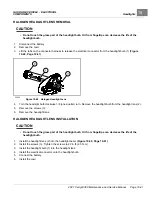
CHARGING DIODE INSTALLATION
CAUTION
• Be sure to remove and discard the protective film from both sides of the thermal pad before installing
it. If not removed, the film will reduce the thermal heat transfer and therefore reduce the power
handling capability of the diode, causing it to overheat and damage the electrical system.
1.
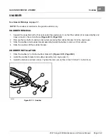
Thoroughly clean and dry the area of the chassis where the new charging diode (7) is to be attached
2.
Peel the protective film from both sides of the new thermal pad (8).
3.
Install the new thermal pad onto the charging diode.
4.
Install the charging diode onto the chassis.
5.
Install the nut (6). Tighten the nut to 25 in·lb (2.8 N·m).
6.
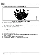
Route and connect the charging diode wires to the solenoid posts in the electrical component box.
See following
WARNING.
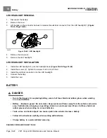
WARNING
• Incorrect wiring could result in severe injury or death.
• Charging diode and solenoid connections must have correct polarity.
• Keep all persons clear of engine belts when making final connections.
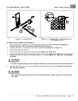
6.1.
Connect the charging diode red wire (4) to the solenoid post with the 4 gauge red wire, 10 gauge red
wire, and 16 gauge orange wire.
6.2.
Connect the charging diode white wire (5) to the other large solenoid post with the 4 gauge white wire, 18
gauge white wire, and 18 gauge red wire.
7.
Install the nuts (3). Tighten the nuts to 55 in·lb (6.2 N·m).
8.
Install the electrical component box cover (2).
9.
Install the screw (1). Tighten the screw to 18 in·lb (2.0 N·m).
10.
Connect the battery and spark plug wire.
Page 19-48
2021 Carryall 300 Maintenance and Service Manual
Summary of Contents for Carryall 300 2021
Page 2: ......
Page 16: ......
Page 551: ...80 2018 by Kohler Co All rights reserved KohlerEngines com 17 690 15 Rev...
Page 565: ...GASOLINE ENGINE HARNESS Wiring Diagrams Gasoline Engine Harness 26...
Page 566: ...Page intentionally left blank...
Page 567: ...GASOLINE KEY START MAIN HARNESS Wiring Diagrams Gasoline Key Start Main Harness 26...
Page 568: ...Page intentionally left blank...
Page 569: ...GASOLINE PEDAL START MAIN HARNESS Wiring Diagrams Gasoline Pedal Start Main Harness 26...
Page 570: ...Page intentionally left blank...
Page 571: ...GASOLINE INSTRUMENT PANEL HARNESS Wiring Diagrams Gasoline Instrument Panel Harness 26...
Page 572: ...Page intentionally left blank...
Page 573: ...GASOLINE FNR HARNESS Wiring Diagrams Gasoline FNR Harness 26...
Page 574: ...Page intentionally left blank...
Page 575: ...ELECTRIC MAIN HARNESS Wiring Diagrams Electric Main Harness 26...
Page 576: ...Page intentionally left blank...
Page 577: ...ELECTRIC INSTRUMENT PANEL HARNESS Wiring Diagrams Electric Instrument Panel Harness 26...
Page 578: ...Page intentionally left blank...
Page 579: ...ELECTRIC ACCESSORIES HARNESS Wiring Diagrams Electric Accessories Harness 26...
Page 580: ...Page intentionally left blank...
Page 588: ...NOTES...
Page 589: ...NOTES...
Page 590: ...NOTES...
Page 591: ...NOTES...
Page 592: ...NOTES...
Page 593: ...NOTES...
Page 594: ...NOTES...
Page 595: ......
Page 596: ......


