12
General Information
ELECTRIC VEHICLE - ELECTRICAL SYSTEM
TROUBLESHOOTING
• The Excel minimum motor braking speed has been lowered to almost zero.
• Excel has higher energy output during regenerative braking due to the lowered minimum motor braking speed.
• The Excel accelerator pedal has more control of downhill speed.
• The programmed speed of the Excel vehicle can now range from 5 to 19.2 mph (8 to 30.8 km/h) with fine
adjustments in 0.1 mph (0.16 km/h) increments.
• Excel provides mileage readings.
• Excel has more diagnostics available.
• Excel offers the ability to change software. Section 11 — Controller Diagnostic Tool (CDT)
KEY DIFFERENCES: EXCEL WITH ERIC CHARGING SYSTEM VS. POWERDRIVE CHARGERS
• Utilizes the 1515-5206 controller (white in color) instead of the 1515-5201 (gray in color).
• New main wire harness (which is not compatible with PowerDrive chargers) that uses a 10k ohm pull-up resistor
for the charger interlock circuit (charger plug lockout pin pulls Lo to lockout the vehicle, and the 10k resistor pulls
Hi once charger plug is removed to enable the vehicle). In addition, the three throttle circuit resistors are now
internal to the controller.
• New B- wire assembly, which replaces the one integral to the onboard computer (OBC). With the OBC gone, the
New B- wire assembly is needed to connect the B- terminal of the controller to the negative (-) post of battery no. 6
(6 x 8-Volt battery set).
• New battery charge indicator light in the instrument panel. This light is an LED and is used to confirm when a charge
cycle begins and when the battery pack has reached a low state of charge.
• New instrument panel wire harness (not compatible with vehicles using PowerDrive chargers)
• A new controller is used that has data collecting functions previously performed by the OBC. Pin 11 in the 16-pin
connector is now utilized to operate the charge indicator light in the instrument panel. In addition, the controller has
mounting slots instead of holes for easier replacement.
• An expanded Monitor menu for CDT: Charge Cycle, Amp-Hours, Faults, and Diagnostics.
• The controller tracks amp-hour usage for fleet management and warranty administration.
• No Communication Display Module (CDM) required. Use only the IQ Display Module (CDT).
• The CDT will remain ON for approximately 10 minutes when the charger is connected.
• Improved charger and battery state of charge (SOC) status indication.
• Battery charger algorithm is programmable in the field via a USB flash drive or laptop computer instead of changing
onboard computer (OBC).
• B+ red wire of charger wire harness now connects directly to the solenoid to reduce potential corrosion.
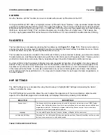
FEATURES
•
Shunt-Wound Motor:
The shunt-wound motor, unlike a series motor, is designed so that the speed controller is
able to vary the amount of current passing through the field coils independently from the current passing through
the armature.
•
Motor Braking:
Under certain conditions a shunt-wound motor also has the ability to act as an electrical brake to
slow the vehicle. There are two features of the Excel electrical system that will activate the motor braking function:
Walk Away Braking and Motor Braking (adjustable with the CDT-P handset).
•
Walk Away Braking:
This feature prevents the vehicle from rolling away uncontrolled should the driver park on a
slope and leave the vehicle without locking the park brake. The vehicle will roll at about 1 to 3 mph (1.5 to 4.8
Page 12-2
2021 Carryall 300 Maintenance and Service Manual
Summary of Contents for Carryall 300 2021
Page 2: ......
Page 16: ......
Page 551: ...80 2018 by Kohler Co All rights reserved KohlerEngines com 17 690 15 Rev...
Page 565: ...GASOLINE ENGINE HARNESS Wiring Diagrams Gasoline Engine Harness 26...
Page 566: ...Page intentionally left blank...
Page 567: ...GASOLINE KEY START MAIN HARNESS Wiring Diagrams Gasoline Key Start Main Harness 26...
Page 568: ...Page intentionally left blank...
Page 569: ...GASOLINE PEDAL START MAIN HARNESS Wiring Diagrams Gasoline Pedal Start Main Harness 26...
Page 570: ...Page intentionally left blank...
Page 571: ...GASOLINE INSTRUMENT PANEL HARNESS Wiring Diagrams Gasoline Instrument Panel Harness 26...
Page 572: ...Page intentionally left blank...
Page 573: ...GASOLINE FNR HARNESS Wiring Diagrams Gasoline FNR Harness 26...
Page 574: ...Page intentionally left blank...
Page 575: ...ELECTRIC MAIN HARNESS Wiring Diagrams Electric Main Harness 26...
Page 576: ...Page intentionally left blank...
Page 577: ...ELECTRIC INSTRUMENT PANEL HARNESS Wiring Diagrams Electric Instrument Panel Harness 26...
Page 578: ...Page intentionally left blank...
Page 579: ...ELECTRIC ACCESSORIES HARNESS Wiring Diagrams Electric Accessories Harness 26...
Page 580: ...Page intentionally left blank...
Page 588: ...NOTES...
Page 589: ...NOTES...
Page 590: ...NOTES...
Page 591: ...NOTES...
Page 592: ...NOTES...
Page 593: ...NOTES...
Page 594: ...NOTES...
Page 595: ......
Page 596: ......


