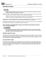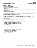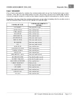
CONTROLLER DIAGNOSTIC TOOL (CDT)
Fault Descriptions
11
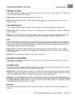
THERMAL CUTBACK
If the controller heatsink temperature is found to be in excess of 185 °F (±9) (85 °C (±5)) or below –13 °F (±9) (–25 °C
(±5)), the
thermal cutback
fault is detected.
What it means:
Heatsink temperature rises above 185 °F (85 °C).
What to do:
Monitor Heatsink Temp, battery voltage, brakes dragging, car under extreme loads, low or no air
pressure in tire(s).
ANTI-TAMPER FAULT
If communication with the Visage or Guardian unit is interrupted, the controller registers an
anti-tamper fault
.
What it means:
This is a symptom, not a cause. The controller is set to communicate with a Visage or Guardian unit
and it is unable to.
What to do:
Clear the Fault History in the CDT. Ensure wiring is connected and inspect for damaged wires. If the
vehicle is not or no longer going to be equipped with these services, change Control Mode setting to zero (0).
HPD
The
HPD
(High Pedal Detect) fault is detected if the accelerator pedal is already depressed when the key switch is
turned to the ON position. This fault is also detected if the accelerator pedal is pressed when the selected direction is
changed by pressing the Forward/Neutral/Reverse control (FNR). This fault, when not caused by the operator, can
indicate that the pedal limit switch has failed closed.
What it means:
The pedal is depressed before the key switch and/or the FNR is switched on. This is a safety
control and the controller must see the pedal engaged last in the following sequence: key switch first, FNR second,
and then pedal last.
What to do:
Check throttle percentage and, if at 0, issue is driver error.
MAIN DRVR OVERCURRENT
If the current on the relay driver exceeds 120 mA, or the current on the solenoid driver exceeds 6 A, a
main driver
overcurrent
fault is detected.
LOCKOUT FAULT
If the controller receives a signal that the charger interlock is activated while the vehicle is being driven, the controller
registers a
lockout fault
and may prevent the vehicle from operating.
What it means:
This is a symptom, not a cause. The controller should only see charger interlock activated when the
charger's DC cord (external charger) is connected to the vehicle or AC cord (onboard charger) is connected to an AC
outlet. One possible cause is failure of the 10k ohm resistor in the charger interlock circuit.
What to do:
Clear the Fault History in the CDT. If the fault does not return and the car operates normally, do not
replace the controller. If the fault continues to occur, inspect and test the charger interlock circuit.
See Test Procedure
10 – Charger Interlock on page 12-24.
If the 10k ohm resistor has failed, replace resistor. If no problems are found
in the charger interlock circuit, replace the controller.
LOW SOC
If the controller sees that the battery pack has reached a low state of charge (SOC), the controller registers a
low
SOC fault
.
2021 Carryall 300 Maintenance and Service Manual
Page 11-19
Summary of Contents for Carryall 300 2021
Page 2: ......
Page 16: ......
Page 551: ...80 2018 by Kohler Co All rights reserved KohlerEngines com 17 690 15 Rev...
Page 565: ...GASOLINE ENGINE HARNESS Wiring Diagrams Gasoline Engine Harness 26...
Page 566: ...Page intentionally left blank...
Page 567: ...GASOLINE KEY START MAIN HARNESS Wiring Diagrams Gasoline Key Start Main Harness 26...
Page 568: ...Page intentionally left blank...
Page 569: ...GASOLINE PEDAL START MAIN HARNESS Wiring Diagrams Gasoline Pedal Start Main Harness 26...
Page 570: ...Page intentionally left blank...
Page 571: ...GASOLINE INSTRUMENT PANEL HARNESS Wiring Diagrams Gasoline Instrument Panel Harness 26...
Page 572: ...Page intentionally left blank...
Page 573: ...GASOLINE FNR HARNESS Wiring Diagrams Gasoline FNR Harness 26...
Page 574: ...Page intentionally left blank...
Page 575: ...ELECTRIC MAIN HARNESS Wiring Diagrams Electric Main Harness 26...
Page 576: ...Page intentionally left blank...
Page 577: ...ELECTRIC INSTRUMENT PANEL HARNESS Wiring Diagrams Electric Instrument Panel Harness 26...
Page 578: ...Page intentionally left blank...
Page 579: ...ELECTRIC ACCESSORIES HARNESS Wiring Diagrams Electric Accessories Harness 26...
Page 580: ...Page intentionally left blank...
Page 588: ...NOTES...
Page 589: ...NOTES...
Page 590: ...NOTES...
Page 591: ...NOTES...
Page 592: ...NOTES...
Page 593: ...NOTES...
Page 594: ...NOTES...
Page 595: ......
Page 596: ......

