11
Monitor Menu
CONTROLLER DIAGNOSTIC TOOL (CDT)
WARNING
• The vehicle operator should not monitor the handset while the vehicle is in motion. A technician
can monitor the handset while traveling as a passenger in the vehicle. Failure to heed this warning
could result in severe personal injury or death.
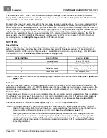
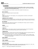
The following parameters can be monitored in real time with the handset from the
Monitor
menu:
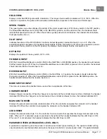
BATT VOLTAGE
Displays the current battery voltage at the speed controller.
V
MIN
I
Displays volts (minimum) at a certain amperage. This is a setting parameter used with the Low SOC (State of
Charge) detection fault.
SIGNED BATTERY CURRENT
While driving the vehicle, this displays either the current being pulled out of the batteries or the current being returned
to the batteries during regenerative motor braking. It has a range from negative (–) 300 amps to positive (+) 300 amps.
BDI PERCENT
Battery Discharge Indicator (BDI) Percent displays the current battery state of charge as a percent. It is based on
several parameters monitored by the controller.
SPEED
Vehicle speed in mph.
THROTTLE
Indicates the position of the accelerator pedal from 0% (pedal not pressed) to between 95 and 100% (pedal fully
pressed). This item can be monitored when the key switch is in the ON or OFF position.
TEMPERATURE
Displays the temperature (in degrees Celsius) of the speed controller heatsink. During normal operating conditions, the
heatsink temperature should be below 185 °F (±9) (85 °C (±5)).
See following NOTE.
NOTE:
Anything that adds resistance (i.e. improper brake adjustment, low air pressure in tires, low battery voltage,
etc.) can cause the operating current to be higher than normal. This higher current increases the temperature
of the speed controller heatsink.
ARM CURRENT
Displays the motor armature current (in amperes).
FIELD CURRENT
Displays the motor field current (in amperes).
ARMATURE PWM
Displays motor armature PWM (pulse width modulation). The range of pulse width modulation is 0% to 100%. When
the vehicle is operating at full speed, the pulse width modulation should be at 100%.
Page 11-10
2021 Carryall 300 Maintenance and Service Manual
Summary of Contents for Carryall 300 2021
Page 2: ......
Page 16: ......
Page 551: ...80 2018 by Kohler Co All rights reserved KohlerEngines com 17 690 15 Rev...
Page 565: ...GASOLINE ENGINE HARNESS Wiring Diagrams Gasoline Engine Harness 26...
Page 566: ...Page intentionally left blank...
Page 567: ...GASOLINE KEY START MAIN HARNESS Wiring Diagrams Gasoline Key Start Main Harness 26...
Page 568: ...Page intentionally left blank...
Page 569: ...GASOLINE PEDAL START MAIN HARNESS Wiring Diagrams Gasoline Pedal Start Main Harness 26...
Page 570: ...Page intentionally left blank...
Page 571: ...GASOLINE INSTRUMENT PANEL HARNESS Wiring Diagrams Gasoline Instrument Panel Harness 26...
Page 572: ...Page intentionally left blank...
Page 573: ...GASOLINE FNR HARNESS Wiring Diagrams Gasoline FNR Harness 26...
Page 574: ...Page intentionally left blank...
Page 575: ...ELECTRIC MAIN HARNESS Wiring Diagrams Electric Main Harness 26...
Page 576: ...Page intentionally left blank...
Page 577: ...ELECTRIC INSTRUMENT PANEL HARNESS Wiring Diagrams Electric Instrument Panel Harness 26...
Page 578: ...Page intentionally left blank...
Page 579: ...ELECTRIC ACCESSORIES HARNESS Wiring Diagrams Electric Accessories Harness 26...
Page 580: ...Page intentionally left blank...
Page 588: ...NOTES...
Page 589: ...NOTES...
Page 590: ...NOTES...
Page 591: ...NOTES...
Page 592: ...NOTES...
Page 593: ...NOTES...
Page 594: ...NOTES...
Page 595: ......
Page 596: ......

