TORQUE CONVERTER
Drive Clutch
2006-2010 Turf/Carryall 272/472 and XRT 1200/1200 SE Maintenance and Service Manual
Page 17-11
17
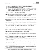
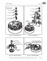
12. Install the 1/4-20 screws and washers (1) and tighten them to 10 ft-lb (13 N·m)
.
See following NOTE.
NOTE:
Make sure there is at least a (minimum) gap of 0.020-inch (0.51-mm) between each end of the
mounting pin and the mounting screw.
13. Install three drive button take-up springs.
13.1. Install each spring on right-hand side of the three button mounting posts (when looking into the
interior of the clutch drive hub, and with a rib at a twelve o’clock position) as shown
14. Compress each take-up spring and install the drive button over the rib and take-up spring
15. Install a no. 10-24 button retaining screw with flat washer through each button and into the rib. Tighten
the screws to 34 in-lb (3.8 N·m)
.
16. Install the thrust washer (11) onto the moveable face assembly
.
17. Install the hub assembly (8) on the moveable face assembly and align the match marks made before dis-
assembling the clutch. Press the hub assembly on by hand.
18. Replace the three plastic plugs (9) into the hole protectors
.
DRIVE CLUTCH INSTALLATION
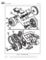
1. Place the drive clutch assembly on the crankshaft taper. Position the flat washer (19) on the bolt (18) and
start the bolt into the crankshaft
.
See following NOTE.
NOTE:
The drive clutch retaining bolt has left-hand threads. The manufacturer recommends replacing the
drive clutch retaining bolt (CC PN 103345701) when installing the drive clutch. If a new bolt is not
available, clean the threads of the original bolt and apply Loctite
®
242 to the threaded end prior to
installation.
2. Tighten the drive clutch retaining bolt (17) to 25 ft-lb (33.9 N·m).
3. Install the starter/generator belt and adjust belt tension as instructed.
See Starter/Generator Installa-
Tighten the starter/generator mounting hardware to 23 ft-lb (31.2 N·m) and
the adjusting hardware to 13 ft-lb (17.6 N·m).
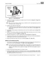
Figure 17-14 Install White Washers
Pin should protrude an equal amount
on both sides.
Install white
washers on
each side
of pin.
Summary of Contents for CARRYALL 272
Page 2: ......
Page 14: ......
Page 18: ...1...
Page 52: ...5...
Page 90: ...6...
Page 110: ...7...
Page 112: ...8...
Page 128: ...10...
Page 170: ...11...
Page 224: ...13...
Page 284: ...16...
Page 302: ...17...
Page 308: ......
Page 309: ...Club Car R NOTES...
Page 310: ...Club Car R NOTES...
Page 311: ......


