Cloos NexT 452 AC Operating Instructions Manual Download Page 187

187

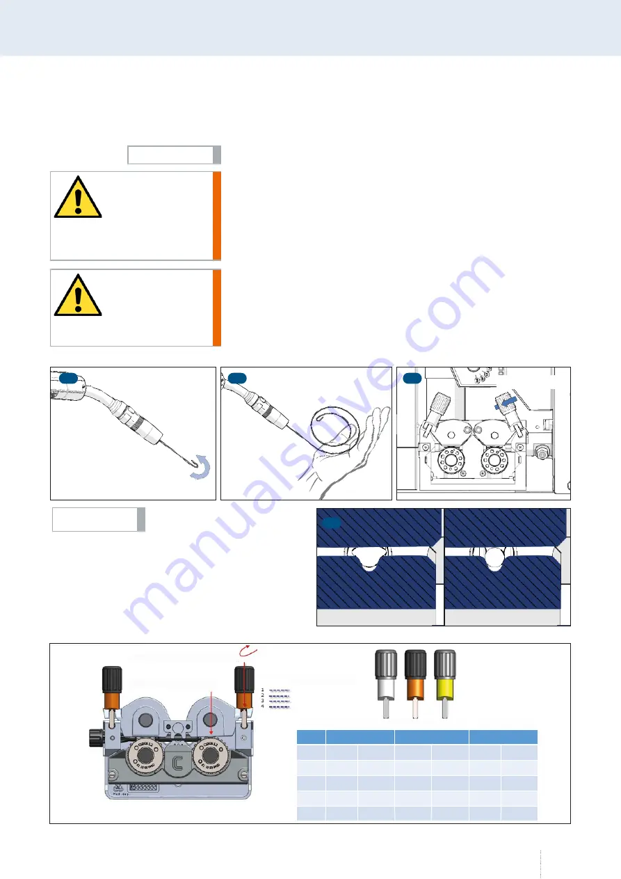
8.5  Adjustment of the pressure clamps

The illustrations may differ from the original.

Stab injury!

In the case of an incorrect handling of the welding torch during the wire 
feeding process, the wire transport may cause stab injuries on hand, eyes 
or the face. 

•  During the wire feeding, you should always keep the welding torch in 

a position turned away from the body! 

Risk of electric shock

If unrestricted access to the live single parts of the QINEO Wire Drive is 
possible, all persons must exercise caution to prevent electric shock or risks 
of electrical energy.

•  Only trained specialists may work on the device.

INFO!

WARNING!

WARNING!

1

½

 rotation

3

2

4

The welding wire must not be 

deformed.

INFO!

 4~85N

F1

F2

4~140N

F1

F2

4~200N

F1

F2

1

20

47

30

71

40

95

2

40

95

60

142

100

236

3

60

142

90

212

160

377

4

80

189

120

283

220

519

Spring tension F1

Pressing force F2

Step

White

Step

Orange

Yellow

Summary of Contents for NexT 452 AC

Page 1: ...Master Premium AC DC OPERATING INSTRUCTIONS QINEO NexT En This is a translation of the original operating instructions BA QN NX 04 20 Rev 3 41 Keep for future use...

Page 2: ...Carl Cloos Schweisstechnik GmbH Carl Cloos Strasse 1 35708 Haiger GERMANY Telephone 49 0 2773 85 0 Telefax 49 0 2773 85 275 E mail info cloos de www cloos de...

Page 3: ...he directives applied is verified with conformance to the following standards and regulations Major conversions and add ons which are not carried out by the manufacturer or the manufacturer s authoris...

Page 4: ......

Page 5: ...24 4 Environmental circumstances 25 4 1 Storage 25 4 2 Transport 26 5 Qualification of users 26 Block 2 Basic information Qineo NexT 27 1 Power source views 28 2 Product description 30 3 Transport 30...

Page 6: ...lse parameters in the Expert Mode 54 6 8 Main Programming Active QWD 55 6 9 Main Programming Welding circuit from x 02 55 7 MAIN Measured values 55 7 1 Operating data 56 7 1 1 Data set switching 1 2 5...

Page 7: ...e unit QWD B 97 10 7 Diagnostics Cooling module 97 10 7 1 Diagnostics cooling module LED 98 10 8 Diagnostics Robot 99 11 MAIN 2 Language 100 12 MAIN 2 Data backup 101 12 1 Data backup Job 101 12 1 1 S...

Page 8: ...onal parameters of operating mode Spot Welding Interval 126 4 2 6 Parameter setting ranges optional 126 4 3 Save and load job 128 4 3 1 Quick memory access 128 4 3 2 Storage management 129 5 Configura...

Page 9: ...INEO Wire Drive M4 169 3 1 Connection overview M4 170 4 QINEO Wire Drive M5 171 4 1 Connection overview M5 172 4 2 Connection instructions cable assembly 173 4 2 1 Preparations on QWD M5 173 4 2 2 Att...

Page 10: ...pen Machine Interface 214 1 2 Profibus Module Process Field Bus 214 1 3 ProfiNet Module 215 1 4 DeviceNet Module 215 1 5 Ethernet IP Module 215 2 QIROX Technology Interface QTI 216 2 1 Software compat...

Page 11: ...11 Block 1 Operational Safety...

Page 12: ...r sources and the accessories in the QINEO series have been developed designed and manufactured according to the generally accepted safety regulations This is confirmed by the declaration of conformit...

Page 13: ...probably dangerous situation which may result in minor injury or damage to property WARNING Describes a probably dangerous situation which may result in severe injury or even death DANGER Describes an...

Page 14: ...s have to be considered Safety regulations BGV D1 Safety regulations BGV A3 National and regional fire protection rules Works on supply voltage repairs and maintenance must be carried out by qualified...

Page 15: ...th arc welding systems in the environment of the power source the feed lines and the torch However the safety values for persons with active implants cardiac pacemakers defibrillators and similar migh...

Page 16: ...ly network It is difficult to guarantee electromagnetic compatibility for class A machines due to conducted emissions and radiated interferences in these areas 3 3 3 Radiation Ultraviolet and infrared...

Page 17: ...y regulations 3 3 5 Fire prevention explosion Remove all flammable materials around the welding place or cover these with a non flammable or at least hardly combustible material Hot slag or spatter mi...

Page 18: ...sioned The negative cable earth cable and the positive cable are locked by turning to the right Loose plugs affect the arc and thus the welding behaviour of the power source to a considerable extent...

Page 19: ...3 grey N Earth conductor blue PE Protective conductor green yellow The terminal voltage of the power source can be up to 113 V DC or 48 V AC Although the power source is marked S for welding in enviro...

Page 20: ...ection In the case of improper mains connection of the machine severe shock currents may arise In connection with the welding power source the protective conductor may be destroyed by faulty mass conn...

Page 21: ...ring welding They may cause the following Overheating of components which are connected to the workpiece Fire risk Destruction of protective conductors Danger to life The two following figures show an...

Page 22: ...the mains cable and in the building installation are hereby destroyed If possible use a potential compensating line with a high cross section Please observe the following points to prevent stray curre...

Page 23: ...e opened or removed during mainte nance or repair works Make sure that during operation all covers and side panels are closed and duly assembled by means of toothed conical spring washers earthing Bef...

Page 24: ...e cooling circuit and damage the coolant pump The manufacturer is not liable for such damages Pay attention to the following notes when opening the cooling circuit Bring the welding torch and the torc...

Page 25: ...y the manufacturer Please observe the national and international standards and regulations regarding the safety check The mounting area should be free of dust and aggressive agents The ground should b...

Page 26: ...xis see label For the transport of the machine it is important to adhere to the valid national and regional guidelines and safety regulations in force Only persons who have been trained and instructed...

Page 27: ...27 Block 2 Basic information Qineo NexT...

Page 28: ...Power source views 1 2 5 4 3 Figure 6 Front view QINEO NexT left and QINEO NexT AC right 1 Main switch 2 Status LED welding power source 3 Status LED cooling unit 4 Level indicator 5 Coolant filler n...

Page 29: ...et X77 8 USB 9 External VBC interface X70 10 Pulse synchronisation and Tandem connection X32 11 Connection external wire drive 12 Mains connection 13 Welding current positive cable 14 Welding current...

Page 30: ...the MoTion Weld pro cess and are used for welding thin medium and thick sheets 3 12 mm Materials to be welded are Quality steel CrNi steel aluminium AlMg AlSi AlMn and copper based materials CuSi AlB...

Page 31: ...key press This enables you to set the exact gas quantity by means of a gas control cone If the button is pressed for more than 0 5 s the function is only active as long as the button is pressed For s...

Page 32: ...led in the cooling system after having connected the welding torch Always use a coolant approved by CLOOS It is not allowed to use chlorinat ed or mineral water because of its electrical conductivity...

Page 33: ...of used electric and electronic units with the unsorted municipal solid waste They have to be collected separately The symbol Dustbin on wheels indicates the necessity of waste separation In Germany o...

Page 34: ...ry V 36 5 36 5 I1 60 primary A 30 5 32 5 S1 60 primary kVA 21 1 22 5 Data 100 duty cycle I2 100 secondary A 350 350 U2 100 secondary V 31 5 31 5 I1 100 primary A 22 22 6 S1 100 primary kVA 14 8 15 7 M...

Page 35: ...8 6 4 MAIN Programming Setting ranges 49 6 4 1 Input of setting ranges 49 6 4 2 Prerequisite to use the setting ranges 50 6 4 3 Deactivating the setting ranges 51 6 5 MAIN Programming Tandem 52 6 6 MA...

Page 36: ...tics Process control Data set info 89 10 5 Diagnostics Power unit 90 10 5 1 Diagnostics Power unit Mains 90 10 5 1 1 Diagnostics Power unit Mains Measured values 91 10 5 2 Diagnostics Power unit Tempe...

Page 37: ...simple operation even when programming extensive welding tasks Item Description 1 Function keys F1 F8 2 Colour LCD display 3 LED arc start 4 Rotary knob 1 power wire speed 5 Keys Esc MAIN job job sel...

Page 38: ...dataset Material Fe CrNi1 4316 AlSi AlMg AlMg4 5 Mn CuSi CuAl Fe Basis Fe Rut Fe Met Wire 0 8 0 9 1 0 1 2 1 4 1 6 2 0 2 4 mm Gas 82 argon 18 CO2 91 argon 4 O2 5 CO2 92 argon 8 CO2 90 argon 10 CO2 95 a...

Page 39: ...oid valve closes after expiration of the gas post flow time 3 2 4 cycle Operating mode 4 cycle is provided for longer manual welds 1st cycle Press torch trigger Solenoid valve for shielding gas opens...

Page 40: ...on on the torch You can find additional information in the chapter 6 2 Parameters in the operating mode Super 4 cycle on page 47 3rd cycle Press torch trigger again The end crater program is executed...

Page 41: ...lled pulsed arc The welding settings are chosen in such a way that a hard and stable pulsed arc arises The welding current depends on the distance between torch and workpiece Arc seam tracking is poss...

Page 42: ...f the control processor This enables exceptionally low spatter welding of thin sheets in the range of approx 0 5 mm 3 0 mm The AC part is set by means of the rotary knob 2 see Figure 9 This pulsed arc...

Page 43: ...am ics and Fine adjustment Arc length CleanStart is always active 5 MAIN Function The display field is highlighted yellow if one function is active 5 1 DuoPulse If the function is active a second weld...

Page 44: ...when the wire is fed further For the Wire forward function on the torch cable assembly the wire speed from the above menu always applies Wire monitoring in the MCU is taken into account here 5 5 Wire...

Page 45: ...c curve is not changed It can always be reset to the original state display 0 In programming mode the following display concept applies Yellow time Green m min step size Red power In the programming m...

Page 46: ...6 1 Parameters in the operating modes 2 cycle and 4 cycle Function Correction value Gas pre flow Off 99 Inching in 99 Start program time Off 99 Start program power 99 Upslope Off 99 Main power Absolu...

Page 47: ...param eters The power continuation is ensured by shortly pressing the torch trigger 0 5 s Use the function Step modulation to determine the step width of the increase or the reduction of the wire spe...

Page 48: ...value between 99 and 99 The appropriate absolute value changes as well 6 3 Parameters in operating mode Spot Welding Interval If the operating mode Spot welding is active you have to enter the values...

Page 49: ...ser management see section 9 4 Access rights on page 70 6 4 1 Input of setting ranges In order to be able to input the setting ranges you have to log on as Con figurator MAIN 2 Log on The setting rang...

Page 50: ...quisite to use the setting ranges As soon as setting ranges are configured they are available for the Pro grammer or Automatic operating levels Activating the setting ranges for the Automatic operatin...

Page 51: ...82 Argon 18 Co2 0 0 Zugangsverwaltung Optionen Bedienlevel Automatik Schweissen freigeben Job aufrufen freigeben Handrad Leist Fein freigeben Job speichern sperren Figure 17 Config Access management...

Page 52: ...ower sources type QINEO NexT Master The Expert Mode is an alternative operating possibility to the synergy mode The Expert Mode requires a fundamental knowledge of the pulsed arc welding process and i...

Page 53: ...parameters use the MAIN or Esc buttons with active Expert Mode You are now in the MAIN menu Always use rotary knob 1 to set the wire speed Use rotary knob 2 to set the most important electrical parame...

Page 54: ...4 DuoPulse parameters in the Expert Mode DuoPulse is not an independent pulsed arc welding process but only a changing between two parameter settings If the Expert Mode function is active the DuoPuls...

Page 55: ...er source has recognised more than one QWD When a QWD is activated wire is fed from the torch in the case of a weld ing start There is a risk of Injury by the sharp wire tip Electric shock when touchi...

Page 56: ...e adjustment speed x10 x100 x1000 Meaningful operating data can only be collected in conjunction with the optional SD sensor in the wire drive The operating data can be displayed on the operating modu...

Page 57: ...ary to increase the seam counter by one Display Messwerte Betriebsdaten Puls 4 Takt V 0 A 1 2 mm Fe 82 Argon 18 Co2 0 0 B E T R I E B S D A T E N Summenz hler Betriebszeit 12 47 Std Verbrauchsdaten ab...

Page 58: ...igure 27 Display Messwerte Verbrauchskosten x 11 Puls 4 Takt V 0 A 1 2 mm Fe 82 Argon 18 Co2 0 0 B E T R I E B S D A T E N Summenz hler Betriebszeit 12 47 Std Kosten ab Reset 1 Schweissn hte 0 Verbrau...

Page 59: ...to be expected Since this is a calculated value the real welding current may differ from the pre announcement The display Vset shows the welding voltage to be expected Since this value has been calcu...

Page 60: ...Co2 0 0 Wasser ber wachung Kompen sation Benutzer verwaltung Ethernet Uhr Prozess ber wachung Display Konfig V 10 Figure 29 Config menu Figure 30 Config General menu Display Konfig Allgemein ab V2 Nex...

Page 61: ...et the speed of the parameter change released by the torch trigger The adjustment is between 1 10 The correction value is 100 ms each Step width Using this function you set the size of the parameter c...

Page 62: ...parameters Arc length Power and Dynamics External process selection is ignored in connection with QTI Designation Function Off If two different processes are executed at the same time with a Tandem t...

Page 63: ...available with AC welding power sources Designation Function Standard Positive pole on welding torch Negative pole on welding torch Recommended when changing to a TIG welding torch or when using spec...

Page 64: ...ettings Sense technology On Off Mode On or Off Sense technology Differential voltage Difference 0 0 V 40 0 V If the adjusted voltage is exceeded the error message Err 25 Sense voltage exceeded appears...

Page 65: ...ction is configured in this menu refer to Figure 34 During threading the wire feed speed is continuously increased In a period of 20 seconds it increases from 0m min to the maximum value Figure 33 Con...

Page 66: ...eneral Options The welding power source is equipped with an option chip Each time when being switched on the processor of the welding power source de tects the activated software options in the option...

Page 67: ...ct the newly activated option is listed in the Activated options overview If an error occurred during the transmission or input of the activation code the error message 317 Wrong activation code appea...

Page 68: ...e coolant can be monitored The limit value is set in C The limit value should not exceed 60 C The start delay allows a trouble free recording of the measured values In addition an error must exist for...

Page 69: ...s the workpiece during the measure ment The measurement process is started on the operating module by means of the rotary knob and is also possible from the torch trigger Proceed as follows in order t...

Page 70: ...Access to the preset values is blocked The user with Automatic operating level does not need an access code Programmer The user with the Programmer operating level can call and look at the individual...

Page 71: ...ned time to the Operating level when switching on You can select between Off and Log out after 1 to 30 min Access management Option In this menu the following access rights can be set for the Automati...

Page 72: ...rce or the operating module must dispose of a PAK port The PAK is connected to the PAK port of the welding power source and the user profile is loaded The user is automatically logged on to the weldin...

Page 73: ...999 which are stored in the welding power source Allowed jobs default The user can only call and use the allowed jobs It is possible to specify defined parameter limits setting ranges within a job fo...

Page 74: ...save jobs after login with your password or PAK Call job Designation Function Enable You can call jobs without login Lock You can only call jobs after login with your password or PAK Rotary knob In th...

Page 75: ...ser Push rotary knob 3 to select a free storage space in the user overview and to save all relevant user data in the Config Edit user menu INFO Puls 4 Takt V 0 A 1 2 mm Fe 82 Argon 18 Co2 0 0 Konfig B...

Page 76: ...t configurator locked appears This prevents the last authorised user from being deleted unintentionally 9 4 2 3 Config User management User overview PAK A PAK can only save one user profile If you sav...

Page 77: ...the desired position for entering numbers The selected number field is highlighted in white You can select a number between 000 and 255 by means of rotary knob 3 Use one of the arrow keys to move to...

Page 78: ...ernal The error message is reset by an external signal OMI or bus system Ignition control If there is no signal Arc existing within 5 seconds after the command Start welding the error message Err 24 A...

Page 79: ...an active job and the next job this is detected and the system will jump back to the job with the position xx1 Example Active job 44 next job 48 job continuation to storage space 41 Terminal process v...

Page 80: ...cs The diagnostics menu provides the following submenus Display Konfig Allgemein 3 ab V10 Puls 4 Takt V 0 A 1 2 mm Fe 82 Argon 18 Co2 0 0 Konfig Allgemein 3 Potistellbereich WIG Min A 0 Max A 0 Figure...

Page 81: ...no Docu no For an error entry the error number and for a documen tation entry the documentation number that identifies the entry Error text Docu text The text belonging to the respective error number...

Page 82: ...Diagnostics System logbook Logbook selection The number of entries indicates the number of logbooks 10 3 Diagnostics Control Software version corresponds to Diagnostics Software version Mod ules NexT...

Page 83: ...utputs during Automatic mode Diagnose Ethernet Puls 4 Takt V 0 A 1 2 mm Fe 82 Argon 18 Co2 0 0 Ethernet Steuerung MAC Adresse 00 00 00 00 00 00 IP Adresse 000 000 000 000 Subnetzmaske 000 000 000 000...

Page 84: ...CollectWarningGr1 CollectWarningGr2 WarningWire Warn ingCurrent WarningVoltage WarningGas WarnMotCurrCK WarnMotCur rCDD WarnWeldTime WarningRes 1 WarningRes 2 SDAbort Sd ready Select signals Use rota...

Page 85: ...tus bits of the inputs and outputs of the VBC module Via the menu item Module Reset you reset the IP address and the subnet mask of the VBC module to 000 000 000 000 Diagnose VBC NexT V x 4 Diagnose V...

Page 86: ...e functionality of the LED by moving the middle rotary knob to mode Diag nostics The parameters can now be changed The LED adapts to the changed values Diagnose Led Diagnose Led Mode Frequenz 0 1 Hz T...

Page 87: ...responds to DSP software see Diagnostics Soft ware version Modules QN DSP D I A G N O S E Tandem Puls 4 Takt V 0 A 1 2 mm Fe 82 Argon 18 Co2 0 0 Gar tekonfiguration Tandem Funktion Aus Tandem Status T...

Page 88: ...Puls 4 Takt V 0 A 1 2 mm Fe 82 Argon 18 Co2 0 0 Synchronisation Modus Taktgeber Frequenz 200 Hz Phasenverschiebung 50 Taktgeber aktiv Synchronisation aktiv Figure 65 Diagnostics Process control Pulse...

Page 89: ...g power source To load further data sets into the welding power source read the chapter 12 MAIN 2 Data backup on page 101 Diagnose Aktuelle Kennlinie St tzpunkte 10 Draht Min 3 5 m min Draht Max 12 0...

Page 90: ...the welding power source of the connected mains supply Diagnose Leistungsteil Inverter Stromnetz Abgleich Temperatur L fter Led Typ Inverter DC Leistung 450 A Software Version 01 03 00 PLD Version 01...

Page 91: ...spannung L1 L2 4 8 V Netzspannung L2 L3 5 0 V Netzspannung L3 L1 5 0 V Netzfrequenz 0 00 Hz Phase L1 2 L2 3 0 Grad Phase L2 3 L3 1 0 Grad Diagnose Messwerte Figure 71 Diagnostics Power unit Mains Meas...

Page 92: ...rieb Sollwert Strom Sollwert Spannung 0 0 V AC Polung Frequenz AC Frequenz 20 Hz Spannungsabsenkung Aus Leistung Aus Diagnose Inverter V 2 03 xxx Figure 74 Diagnostics Power unit Inverter in operation...

Page 93: ...iagnose L fter L fter Modus AC L fter Modus 0 Aus Betrieb L fter Inverter Modus Sollwert Drehzahl Istwert 0 U min berwachung L fter AC Modul Modus Sollwert Drehzahl Istwert 0 U min berwachung 0 Betrie...

Page 94: ...le rotary knob The parameters can now be changed The LED adapts to the changed values Diagnose Led Diagnose Led Mode Frequenz 0 1 Hz Tastverh ltnis 100 Rot 10 Gr n 0 Blau 0 Diagnose Figure 78 Diagnost...

Page 95: ...purposes During this process the other nodes along the wire section remain inactive Before starting with diagnosis ensure that either no wire is inserted or the pressure rollers are open Otherwise err...

Page 96: ...onal options that might be enabled If the signal state is 1 On the corresponding box is highlight ed in yellow This menu is also displayed as a submenu for the QWD A Ventile Tasten Optionen Diagnose Q...

Page 97: ...h water sensors The pump and fan can be started or stopped in diagnostics mode using the function Pump fan mode Diagnose QWD B Puls 4 Takt V 0 A 1 2 mm Fe 82 Argon 18 Co2 0 0 Typ QN WD B1_1 Software V...

Page 98: ...ddle rotary knob The parameters can now be changed The LED adapts to the changed values Diagnose Led Diagnose Led Mode Frequenz 0 1 Hz Tastverh ltnis 100 Rot 10 Gr n 0 Blau 0 Diagnose Figure 86 Diagno...

Page 99: ...etc This counter is off during job mode Commands Special commands determine the protocol version switch etc Connections Number of the connection attempts VBC command digital Number of the digital wel...

Page 100: ...ard slot underneath rotary knob 3 Press the function Read from card All language files on the SD memory card are displayed Select the required language file by means of rotary knob 3 and confirm the s...

Page 101: ...o called jobs can be written from the welding power source to the storage medium or from the storage medium to the job memory of the welding power source INFO Datensicherung Qineo NexT V1 03 31 Job D...

Page 102: ...quentially Use the function from Job to select the beginning of the block e g Job 1 The display shows Block Start and the selected job number in yellow Now select the end of the block by means of the...

Page 103: ...oad button The jobs are saved in the job memory of the welding power source Datensicherung JOB Qineo NexT V1 03 xx Laden Von Datei Auswahl Bis Datei Details Alle ausw hlen Memory Card Job Puls 4 Takt...

Page 104: ...e the files to the storage medium After a successful saving the cor responding configuration file is marked with a green tick If a file was skipped a white line appears at the respective position If a...

Page 105: ...7 Data backup Load config from storage medium menu 12 3 Data backup Synergy Datensicherung Synergie Qineo NexT V1 03 xx Lade von USB Speichern Speichere auf USB Laden Datensicherung Synergie Puls 4 Ta...

Page 106: ...tion The current operating level is shown in the upper part of the display You can now enter your personal access code in the lower part of the dis play The access code is activated by pressing rotary...

Page 107: ...of rotary knob 3 The Job name function takes you to the Text input menu 10 10 L schen Job Name Job speichern V 2 03 xx 1 2 3 4 5 6 7 8 9 1 Figure 100 Save job menu Figure 101 Text input menu ABC abc...

Page 108: ...e required character in the character table Shortly press rotary knob 3 to transfer the character to the upper line Once you have selected all characters confirm your selection with the Enter function...

Page 109: ...he selected job The LED on the job button lights up The job number and job name are displayed in the lower part of the MAIN menu If you want to activate another job tap the job button again You are no...

Page 110: ...110 Job mode...

Page 111: ...iagnostics Power unit LED 119 3 5 3 Diagnostics Cooling module 119 3 5 4 Diagnostics Process control 119 3 6 Functions Information 119 3 7 Functions Loading Saving 120 4 Operation 121 4 1 Operating co...

Page 112: ...135 5 3 4 Job continuation 135 5 4 Config General 2 136 5 4 1 Wire speed in 136 5 4 2 V display shows 136 5 4 3 Gas flow min max 136 5 4 4 TIG pot setting range min max 136 5 5 Compensation of the ex...

Page 113: ...ment or dynamics VNominal in Syn Off mode lock unlock 8 12 9 10 11 13 14 15 Figure 102 Display 15 Position Designation Function 8 Welding process Display active process 9 Operating mode Display active...

Page 114: ...n the characteristic curve The arc becomes softer and wider The arc becomes concentrated and smaller During the normal MAG process the shape of the arc is influenced in the dynamic range In the Rapid...

Page 115: ...ee MIG MAG welding process with synergy function It offers a stable metal transfer from short arc to spray arc Rapid Weld modified Control Weld This is a modified Control Weld welding process A very c...

Page 116: ...able for high welding speeds and is ideal for joining sheet metal parts from 0 1 5 mm The welding current depends on the distance be tween torch and workpiece Arc seam tracking is pos sible in connect...

Page 117: ...arance of the weld seam surface is formed by the defined change of parameters During root welding defined cool down times are reached depending on the setting If the DuoPulse function is activated the...

Page 118: ...at regular intervals as the storage space is limited Using the QDM software there are two options Via the backup functions or the management functions The system logbooks are allocated to a certain we...

Page 119: ...the fan which is in the power unit is indicated AC Fan If an AC power unit is installed a separate fan diagnostics is displayed 3 5 2 6 Diagnostics Power unit LED In this menu you test the functionali...

Page 120: ...is saved on the external storage medium The DSA function saves the data set number of the characteristic curve data set in the Synergie syn file on the external storage medium Load characteristic curv...

Page 121: ...e is applied on wire electrode Wire drive unit starts with reduced speed inching in Arc ignites welding current flows Wire drive unit switches to the preset speed 2nd cycle Release torch trigger Wire...

Page 122: ...ecuted with the adjusted parameters and then switches via a programmable time function Upslope to the main program 3rd cycle Press and hold torch trigger Change from main program to the end program vi...

Page 123: ...ap torch trigger Depending on the configuration of the Step modulation and Num ber of steps parameters the power and wire feed speed are increased or reduced with each press of the button on the torch...

Page 124: ...s These default values can be adjusted in the secondary parameters menu 4 2 1 Adjusting secondary parameters 1 Press the menu button 2 Use the left rotary knob to select the menu for the secondary par...

Page 125: ...e rotary knob and confirm by pressing the knob 4 2 3 Parameters of operating modes 2 cycle and 4 cycle Gas pre flow duration Correction value Off 99 Inching in Correction value 99 Start time duration...

Page 126: ...essed for the increase or reduction When the maximum number of steps is reached the power is changed in the opposite direction each time the button is pressed 4 2 5 Additional parameters of operating...

Page 127: ...f the function Power is enabled in addition the setting ranges for start main and end crater power are also active All other adjustment parameters are blocked Blue bars at the bottom of the main displ...

Page 128: ...a welding circuit is car ried out in the configuration menu under menu item Compensation see chapter 5 5 Compensation of the external welding circuit on page 136 4 3 Save and load job Individual user...

Page 129: ...tart screen press the menu button 2 Turn the rotary knob to select a storage space 3 Press the left rotary knob for approx 4 seconds until the selected field turns yellow and DEL appears Deactivate ac...

Page 130: ...g the knob A list of the storage spaces will appear 2 Select an empty storage space using the rotary knob and confirm your selection by pressing the knob An input mask appears The following functions...

Page 131: ...tivate an active job keep the job button pressed until the storage management appears 2 Using the rotary knob select the Job off menu and confirm the selection by pressing the knob The storage managem...

Page 132: ...e card slot above the operating module 2 Select a storage space to be assigned a language The following functions appear Activate Load Delete Cancel If a language is already assigned to this storage s...

Page 133: ...st have the following dimensions Width 479 pixels Height 167 pixels 5 2 2 2 cycle start and end crater program For welding application it is rarely necessary to use the start and end crater programs e...

Page 134: ...into consideration when switching the process 5 2 6 Reset to factory setting Press and hold the knob to reset the settings When resetting to the factory settings all configuration points are reset to...

Page 135: ...he torch trigger The adjustment is between 1 20 The correction value is 0 1 m min each for the Power and 1 each for the Fine and Dynamic parameters 5 3 3 Cooling water pump If an external cooling is c...

Page 136: ...e welding power source To validate the welding power source the terminal voltage must be set here Otherwise the voltage display will be incorrect 5 4 3 Gas flow min max Herewith you determine the mini...

Page 137: ...ng current is fed in Measurement is finished after approx 1 second If it was successful the measured values are automatically displayed So they can be compared with already stored values 5 Repeat the...

Page 138: ...in case of a trou ble signal The monitoring is configured as follows Function Description Off Reset on Start The error message is reset at the next Welding start signal Reset from ex ternal Reset of e...

Page 139: ...efine how long a threshold value is exceeded in seconds until an error message is triggered For example 1 5 2 seconds 5 8 Sense technology This function is only effective in the Control Weld MAG norma...

Page 140: ...e wire drive unit nearest to the wire storage to be the signal transmitter QWD contact sensor ring sensor 2 Welding power source waits for the selected sensor signal from QWD A QWDBx_1 contact sensor...

Page 141: ...t The access management differentiates between two operating levels Blocked Enabled Use this menu to configure which functions are available for the user in blocked status and whether an access code m...

Page 142: ...rights to certain functions adjustments and welding parameters are enabled or blocked and saved in a user profile via the user management If a user logs in who is unknown to the welding power source...

Page 143: ...e welding power source After login Welding is only enabled after login at the welding power source Job range enable Allowed jobs The user has only access to the job range defined in the user profile A...

Page 144: ...emory spaces jobs is enabled Save Job Save S1 S5 Locked The storage on quick memory spaces jobs is blocked Allowed The storage on quick memory spaces jobs is enabled If the option Job memory MasterPlu...

Page 145: ...characters an allowed job range of at least 1 to max 994 jobs a defined operating level 6 Give the user profile a name 7 Specify a password The password must be unique It must not be used for another...

Page 146: ...corresponding PAK port The requested user profile is now transferred to the PAK 5 11 PC adaptation A connection between the welding power source and the software QDM can be established using the Ethe...

Page 147: ...by means of the rotary knob 5 15 Off Re start In this menu you can switch off or restart the welding power source via the operating module 1 Use the rotary knob to select a corresponding function for...

Page 148: ...148...

Page 149: ...149 Block 4 Additional information...

Page 150: ...Figure 108 RC Plus 1 2 7 8 5 3 6 4 1 Quick save memory keys 1 4 2 Multi functional key hold value display selection actual value display 3 Selection key Processes 4 Selection key Operating modes 5 Jo...

Page 151: ...the configuration menu of the welding power source to determine which of the setting parameters shall be changed in which step width and speed by means of the additional buttons For more information...

Page 152: ...3 SD ber wachung M A I N 3 Puls 4 Takt V 0 A 1 2 mm Fe 82 Argon 18 Co2 0 0 SD ber wachung M A I N 3 Puls 4 Takt V 0 A 1 2 mm Fe 82 Argon 18 Co2 0 0 Figure 112 Menu 3 SD module 3 1 Monitoring channels...

Page 153: ...at the QWD feed capacity is too high if the measured value is below the set value So the CDD ROB wire drive unit slows down It may be an indication that the QWD feed capacity is too low or the frictio...

Page 154: ...sensor signal Ignition After the start command given by the robot or the peripheral equipment PLC the signal Arc on must be transmitted within the selected ignition time from the power source control...

Page 155: ...bus system Profi Bus Profi Net Device Net is necessary to transmit digital data to the reserve channels of the SD module The value range is divided into LowByte and HighByte and is preset from 0 to 10...

Page 156: ...es Load Default values of an SD configuration Enter a component name Reset the seam counter to 0 Or change the value of the seam counter via the middle rotary knob manually You can enter a 20 digit na...

Page 157: ...g channels can be combined in groups Thus it is possible to allocate different priorities to the individual monitoring channels Turn the middle rotary knob to select a monitoring channel Press the mid...

Page 158: ...er Set value The value specifies the expected actual value Warning range The value e g 5 A indicates the section from the warning range to the limit range where a warning message is displayed in the o...

Page 159: ...12 Zeit 7 8 Sec Drahtvorschub 11 4 m min Strom 255 A Spannung 35 V Gas 14 8 l min Motorstrom QWD 1 5 A Logbuch Auswahl Keine Fehler Puls 4 Takt V 0 A 1 2 mm Fe 82 Argon 18 Co2 0 0 Puls 4 Takt V 0 A 1...

Page 160: ...A 1 2 mm Fe 82 Argon 18 Co2 0 0 13 12 2010 L O G B U C H Uhrzeit 10 35 47 5 11 Bauteil Unterbodengruppe Naht 12 Job 10 ohne Pulse Zeit 7 8 Sec Drahtvorschub 11 4 m min Strom 255 A Spannung 35 V Gas 14...

Page 161: ...tails Normal 4 Takt V 0 A 1 2 mm Fe 82 Argon 18 Co2 0 0 13 12 2010 F E H L E R Uhrzeit 10 35 47 1 2 Bauteil Unterbodengruppe Naht 12 Zeitpkt 4 8 Sec Dauer 1 8 Sec Drahtvorschub Grenzwert Max 12 4 m mi...

Page 162: ...ing 3 Select and confirm a monitoring channel using the middle rotary knob The submenu SD data opens 4 Turn the middle rotary knob to allocate a group to the monitoring channel 5 Use the arrow keys to...

Page 163: ...ions oder Fehler Eintrag in das aktuelle SD Logbuch Start Schwei prozess blaue LED leuchtet Einschleichen Liste 1 Zeit Achse berwachung SD Schwei zeit berwach Startverz gerung Schwei parameter Z nd be...

Page 164: ...164 SD module...

Page 165: ...s on QWD M5 174 5 QINEO Wire Drive A4 175 5 1 Structure and function A4 176 6 QINEO Wire Drive AR4 177 6 1 Connection overview AR4 178 7 Function 179 7 1 Button Gas manually 179 7 1 1 Adjustment of th...

Page 166: ...tions Wire feed unit QN WF 22 QN WF 32 QN WF 64 Transport and storage 30 C 60 C 20 C 85 C 20 C 50 C Relative air humidity up to 90 at 20 C up to 50 at 40 C 20 80 1 4 Compatibility list Information on...

Page 167: ...vers The wire coil must be secured on the wire coil holder with the locking head to prevent it falling off Options Remote control connection Protective shield Flow meter EURO connection Can be used on...

Page 168: ...cable assembly connection 2 Torch cooling flow 3 Torch cooling return 4 Welding current connection 5 Quick coupling cooling return 6 Quick coupling cooling flow 7 Quick coupling gas 8 Socket to contr...

Page 169: ...files to stiffen the housing The interior of the wire drive unit is accessible via a stable cover which is fastened on the housing body by means of solid hinges For safety reasons the cover is equippe...

Page 170: ...ssembly connection 2 Torch cooling flow 3 Torch cooling return 4 Wire inlet 5 Welding current connection 6 Quick coupling cooling return 7 Quick coupling cooling flow 8 Quick coupling gas 9 Socket to...

Page 171: ...ousing body by means of solid hinges For safety reasons the cover is equipped with a spring damper It is suitable for industrial use Options Flow meter EURO DINSE connection Carriage Remote control co...

Page 172: ...4 5 Optional connector sockets RC ECO MHW xxx TQ MHW xxx Master RC ECO RC Master RPU RC Plus MHW xxx Premium 6 Socket for optional SZ connec tion 7 Wire inlet wire drum 8 Opening for VSP connecting ca...

Page 173: ...Connection instructions cable assembly Follow the steps below to connect the CMW CMG cable assembly 4 2 1 Preparations on QWD M5 5 7 2 6 3 Hex key 6 AF 4 Open ended wrench 14 AF 8 Star screwdriver 25...

Page 174: ...mp screw to adjust the braking force of the wire coil holder so that it does not run when the motor brakes and no wire windings fall off the coil possibly resulting in kinking or short circuits If the...

Page 175: ...QINEO Wire Drive A was specially developed for industrial robot appli cations Options EURO DINSE connection Weld data monitoring CLOOS Duo Drive CDD Wire end control Installation kit A4 MoTion CLOOS M...

Page 176: ...ard 9 Button Wire backward 10 Cooling water connection red 11 Cooling water connection blue 12 Power connection 13 Cooling water connection blue 14 QN WF 22 HD 15 Cooling water connection red 16 Gas c...

Page 177: ...t of industrial robots This ensures an optimum welding wire feed especially in the field of hollow shaft robots Despite the comprehensive equipment with different sensors for weld data monitoring it i...

Page 178: ...ection 6 Connection for collision protec tion gas nozzle sensor etc 7 Connection nipple blow out optional 8 Torch cooling flow 9 Torch cooling return 10 Wire inlet 11 Connection nipple blow out 12 Coo...

Page 179: ...This function enables the exact adjustment of the gas flow rate by means of a gas measuring tube 7 1 1 Adjustment of the gas flow rate Designation Function Gas measuring tube Measurement of the gas e...

Page 180: ...tons is pressed the wire feed motor switches on and accelerates from 1 m min to 7 m min in 3 seconds The welding wire is fed forward or backward The buttons are located on the inside or front of the w...

Page 181: ...g loose hair can be caught by the drive rollers and cause severe injuries Wear fitted work clothing Do not wear jewellery Pull your hair back when working 8 1 2 Risks due to electrical hazards Risk of...

Page 182: ...gas flow to the litre scale of the pressure reducer on the gas cylinder In the case that a company is working with a central gas supply inlet pres sure 6 8bar the welding torch will not be provided wi...

Page 183: ...use stab injuries on hand eyes or the face During the wire feeding you should always keep the welding torch in a position turned away from the body Please take care that the current tip is removed fro...

Page 184: ...184 General commissioning 8 3 2 QWD P5 QWD M5 The illustrations may differ from the original INFO 4 3 2 1...

Page 185: ...turned away from the body Please take care that the current tip is removed from the torch Isolate the welding power source from the power supply before you start the change To obtain a perfect welding...

Page 186: ...186 General commissioning 8 4 2 QWD P5 QWD M5 The illustrations may differ from the original INFO The wire inlet must not touch the wire drive roller INFO...

Page 187: ...d away from the body Risk of electric shock If unrestricted access to the live single parts of the QINEO Wire Drive is possible all persons must exercise caution to prevent electric shock or risks of...

Page 188: ...or defects which may lead to a hazard Prior to each start of the QINEO Wire drive please check The correct mounting of the current tip The correct mounting of the gas nozzle The screw connection of th...

Page 189: ...nt at the pressure clamps Drive rollers worn Correct the pressure adjustment Change the drive rollers Undesired continuous wire feed or gas escape Button is possibly stuck because of dirt or deposits...

Page 190: ...lin de Make sure to provide for safe and environmentally sound disposal of consumables and operational materials According to European directives Directive 2002 96 EC of the European Parliament and Co...

Page 191: ...191 Block 6a Error messages...

Page 192: ...0 C Start Blechdicke 8 5 mm ASet 230 A VSet 27 9 V Synergie Betr Verfahren Funktion M A I N Progr Messwerte Anzeige Puls 4 Takt V 0 A 1 2 mm Fe 82 Argon 18 Co2 0 0 F E H L E R 1 Fehlermeldung CAN Bus...

Page 193: ...connections Service 7 Error when loading the version data Operating module cannot call up the information of the control Switch machine Off and On Check cable connections Service 8 Error during trans...

Page 194: ...re version remote control out of date Software update required Software update Service 44 Software version VBC DeviceNet out of date Software update required Software update Service 45 VBC DeviceNet m...

Page 195: ...date Software update required Software update Service 61 Software version QWD1 out of date Software update required Software update Service 62 Software version QWD2 out of date Software update require...

Page 196: ...carrier Service 189 No enable from control computer Time of initialisation in control computer exceeded 25 seconds Switch machine Off and On Check software for compatibility Service 190 Transmission...

Page 197: ...Switch machine Off and On Check cable connections Service 245 Please switch back on If values in the configuration have been changed that require a restart Perform a restart 250 QWD1 No controller dat...

Page 198: ...ed Preset rotation speed not reached Encoder signals faulty motor movement Check motor movement Check wire feed distance Check encoder Fuse 42V supply faulty Power supply board Service 262 CDD1 Desire...

Page 199: ...the other Software update may be required Service 272 Error in file format Faulty file Use correct file format Service 274 QWD1 Overcurrent Overload results in increased current load of the drive uni...

Page 200: ...or when importing data in option chip Enter new option chip code Use new option chip Service 316 Wrong option chip Option chip is not recognised Use new option chip Service 317 Wrong activation code W...

Page 201: ...g and connections Service 504 Error fan AC module Fan failed Check plug and connections Service 505 Mains Phase failure Uneven voltage due to phase failure Service 506 Mains Undervoltage Mains voltage...

Page 202: ...lass Unknown power class Service 534 Error when loading the alignment values The set values do not match the checksum Service 535 Error inverter PLD Only for CW processes Error during re ignition afte...

Page 203: ...B stick not found Data carrier missing faulty Check data carrier Insert data carrier again Service 621 Internal USB stick is write protected Data carrier faulty Check data carrier Insert data carrier...

Page 204: ...V1 00 00 Check software version Software update Service 705 QWD B3 1 failed Connection to the module interrupted during operation Switch machine Off and On Check plug and connections Service 706 Softw...

Page 205: ...failed Connection to the module interrupted during operation Switch machine Off and On Check plug and connections Service 755 CMD2 failed Connection to the module interrupted during operation Switch m...

Page 206: ...lty motor movement Check motor movement Check wire feed distance Check encoder Fuse 42V supply faulty Power supply board Service 765 Speed error CMD4 Preset rotation speed not reached Encoder signals...

Page 207: ...207 Block 6b General maintenance instructions...

Page 208: ...208 1 Maintenance and Care 1 7 4 5 2 3 8 10 Optional external cooling unit 10 9 Optional lifting eyes 3 11...

Page 209: ...ozzle base gas distributor current tip and gas nozzle Clean current tip and gas nozzle from dirt Damages and intact insulation of the torch neck of the manual welding torch Contact a qualified electri...

Page 210: ...e mentioned testing instructions the corresponding state laws regulations have to be met Control Remedy Weekly 2 The perfect function of the operating interface signal and control LEDs Contact a quali...

Page 211: ...he filter mat If the filter mat is very dirty change it Only use original CLOOS parts 1 4 2 Lifting eyes at the wire drive unit Check the lifting eyes for damages once a month If they are damaged chan...

Page 212: ...212...

Page 213: ...213 Block 7 Automation...

Page 214: ...r or connection to special purpose welding systems Field buses are industrial communication systems using different me dia such as copper cables fibre optic cables LWL and radio wireless By means of a...

Page 215: ...es for the supply of the DeviceNet bus participants with 24 Volt operating voltage The bus participants can be supplied with power by bus or an external source The maximum length of the DeviceNet cabl...

Page 216: ...ion It must be observed that in Tandem operation welding power sources with the protocol type 1 only support the Tandem process Tandem job selection Welding power sources with protocol type 2 support...

Page 217: ...or example with a robot The second welding power source is configured as Slave and is only connected with the Master welding power source 3 2 Conditions All welding power sources involved fulfilled th...

Page 218: ...side Arc adaptation 1 always master welding power source length correction more wire shorter arc Arc adaptation 2 always slave welding power source length correction more wire shorter arc Dynamics 1...

Page 219: ...the robot shall only set the job number but no other parameters 2 If the robot shall set the two parameters Arc length and Power 3 If the robot shall set the three parameters Arc length Power and Dyna...

Page 220: ...ion Welding power sources with protocol type 2 support additional welding processes such as Tandem f f see 2 3 Additional welding processes protocol type 2 on page 216 INFO INFO Synergie Betr Verfahre...

Page 221: ...slave welds Both gas valves open only the slave arc is monitored the two welding power sources are monitored S torch single wire torch T torch Tandem torch In the Tandem operating mode the S Pulse and...

Page 222: ...combinations please contact CLOOS department for Application Engineering The single wire process variants are named Standard It is recommended to adjust the option Tandem following in the slave weldi...

Page 223: ...tandard MIG MAG torch As an example the Tandem torch is connected to QWD1 and a single wire torch to QWD2 With a corresponding torch changing system you can automatically change between the torches Pr...

Page 224: ...Argon 18 Co2 0 0 P R O G R A M M I E R E N Startleistung Dyn 6 0 m min 0 6 2 Stell bereich Tandem Aktiver QWD Expert Mode Impuls Sync Puls 4 Takt V 0 A 1 2 mm Fe 82 Argon 18 Co2 0 0 Programmieren Akt...

Page 225: ...determine which QWD is actuated by the welding power source Name Function QWD number 1 4 The welding power source activates QWD1 4 for welding Puls 4 Takt V 0 A 1 2 mm Fe 82 Argon 18 Co2 0 0 Programm...

Page 226: ...s always corresponds to the own pulse time of the machine set by the synergy characteristic curve Every welding power source can set the frequency as pulse generator or as pulse receiver synchronise t...

Page 227: ...power source is available for synchronisation Pulse receiver The welding power source executes its pulses at the configured time depending on the pulse generator Asynchronous The allocation of pulse g...

Page 228: ...lf of the pulse frequency Pulse receiver alternating The welding power source executes the pulse with a time delay before or after the pulse of the pulse generator The offset depends on the set phase...

Page 229: ...ly synchronised pulse mode has a mostly positive influence on the process stability Pulse generator f1 Pulse receiver f2 alternating b2 Alternating 1 2 f1 f2 With this adjustment the time delayed sync...

Page 230: ...synchronisation is used in connection with two or more in dividual processes a corresponding job has to be called in the welding power sources The following scenarios can be realised using the exampl...

Page 231: ...ection job selection must remain identical in the robot controller Job number Wire in front Wire in the back Operating mode Tandem Seam tracking signal Synergy variant Pulse synchronisation Process Ma...

Page 232: ...232...

Page 233: ...233...

Page 234: ...www qineo de...

Reviews: