ClimaCheck Gateway NX400 Hardware Manual
–
2020-03-26 Page 36 of 41
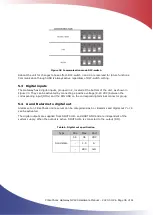
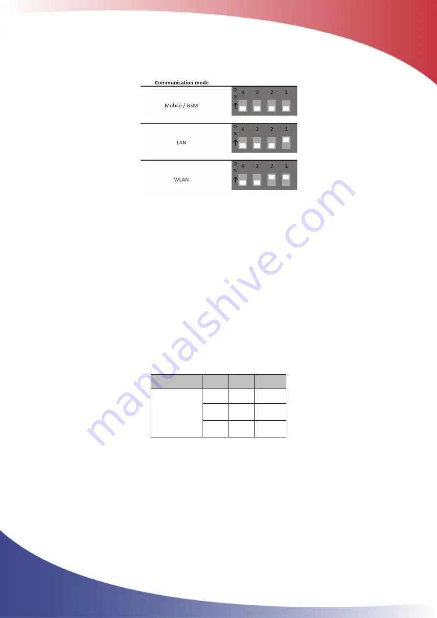
Figure 28 Communication mode DIP-switch
Reboot the unit for changes to take effect. DIP-switch 3 and 4 are reserved for future functions.
Communication through USB is always active regardless of DIP-switch setting.
5.3
Digital inputs
The Gateway has 8 digital inputs, grouped in 2, located at the bottom of the unit, as shown in
Figure 30. They can be activated by connecting a positive voltage (8-40 VDC) between the
corresponding input (DINx) and the DIN GND on the corresponding terminal connector group.
5.4
A and B alarms to digital out
Alarms set on ClimaCheck online server can be categorised as A or B alarms and digital out 7 or 8
can be activated.
The digital outputs are supplied from DOUT SUP+ and DOUT GND and are independent of the
system supply. When the output is active, DOUT SUP+ is connected to the output (DO).
Table 6, Digital out specification
Type
Min
Max
Unit
Solid state
5.5
36
VDC
-
1.5
A
-
280
mΩ

