5
TRANSDUCER DISASSEMBLY
Remove the ring gear and transducer assembly from the rear
of the transducer housing. Press drive shaft No. 203703 or
203704, out of the transducer bearing No. 847566. Remove the
retainer ring No. 619017, from the transducer and tap lightly on
a soft surface to remove bearing, No. 847566. Drive the roll pin
No. 202888, into the transducer until it falls inside the trans-
ducer. Then remove the transducer from the rear of the ring
gear. Note: The transducer is a very delicate part and must be
handled very carefully.
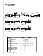
GEAR TRAIN DISASSEMBLY
Single Reduction
The spider should be pressed out the rear of the gear case.
Remove the retainer ring, No. 844364, and press the bearing,
No. 847147, out the front of the gear case.
If replacement of the idler gear pins is necessary, they should
be pressed out the rear of the spider. See Fig. 1 for replacement
pin height.
Fig. 1—Single Reduction Spider
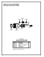
Double Reduction
Both spiders should be removed from the rear of gear case.
Remove the retainer ring, No. 844364, and press the bearing, No.
847147, out the front of the gear case.
If replacement of the idler gear pins is necessary, they should
be pressed out the rear of the spider. See Fig .2 for replacement
pin height.
- 10 & - 104 2nd Reduction Spider - 10 & - 104
1st Reduction Spider
Fig. 2—Double Reduction Spiders
LIGHT RING KIT and HOUSING SHROUD DISASSEMBLY
Remove inlet bushing No. 203355, and slide back exhaust
deflector No. 203356. Unplug wiring and remove wire bundle
No. 203372. All caps and throttle lever must be removed from
backhead No. 203745 or No. 203979, before housing shroud
No. 203742 or 203982 and 203981, can be removed. Loosen
all three set screws No. 843518 and (2)No. 847282, in light ring
several turns. Slide housing shroud off the rear of the backhead.
NOTE: Do not rotate the light ring kit or housing shroud when
removing from backhead to prevent breaking wires. Hold pig
tail connection while removing light ring kit and housing shroud
from backhead.
SERVICE INSTRUCTIONS
DISASSEMBLY—GENERAL (ALL MODELS)
Disconnect tool from air supply. On the "M" and "K" head
unscrew (left hand threads) and remove the right angle head
and the angle head adapter No. 869034. On the "P" head
unscrew housing lock nut No. 203438, lift up and remove the
angle head. Unscrew and remove the second reduction gear
train. Unscrew the inlet bushing No. 203355 and lift exhaust
deflector far enough to unplug wire bundle No. 203372. Un-
screw valve caps(3) No. 203362, No. 832207 and No. 203360.
Remove throttle lever No. 867877. Remove throttle valve and all
related parts. Remove housing shroud or shrouds, from rear
of backhead, being very careful to prevent damage to the wiring.
Unscrew (left hand threads) transducer housing and lift care-
fully, feeding the wiring through the hole in the backhead. To
remove motor assembly, tap backhead lightly on a soft surface.
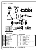
RIGHT ANGLE HEAD DISASSEMBLY
"K" Right Angle Head
To disassemble the right angle head, unscrew the spindle
bearing cap. This will permit the removal of the spindle assem-
bly.
The pinion bearing retainer No. 863564, may be removed by
utilizing a 5/8" hex nut and a 5/8" deep socket. Drop the hex nut
over the pinion shaft and engage the hex in the bearing retainer
and unscrew the retainer using the deep socket. Using a
suitable driver, drive the pinion No. 202200, and related bear-
ings out of the angle head.
"M" Right Angle Head
Using a suitable spanner wrench, unscrew (left hand threads)
the bearing cap No. 864396. Remove the spindle, ball bearing
No. 842517, and driven gear by clamping the spindle in a vise
and driving the right angle housing No. 869048, away from the
spindle using a soft-faced mallet. The ball bearing can now be
removed by pressing the larger end of the spindle through the
bearing I.D. Press the smaller end of the spindle through the
gear to remove the driven gear. The pinion bearing retainer No.
863564, may be removed by utilizing a 5/8" hex nut and a 5/8"
deep socket. Engage the hex in the bearing retainer and
unscrew the retainer using the 5/8" deep socket. The pinion and
bearings may now be removed by lightly tapping angle head on
a soft surface.
"P" Right Angle Head
Using a suitable wrench, unscrew (left hand threads) the
bearing cap, No. 203250. Remove the square drive spindle No.
203249 or No. 203439, ball bearing, No. 842517, and driven
gear No. 203251, by clamping the square drive in the vise. Drive
the right angle housing, No. 203441, away from the square
drive using a soft-faced mallet. Remove the spindle retainer
nut, No. 203248. The ball bearing can now be removed by
pressing the threaded end of the spindle through the gear to
remove the driven gear. Remove the housing set screw No.
867546, and using a punch, drive the pinion gear No. 203440,
and bearings No. 203253 and 202197 out the angle head.
.240
.255
Front
Rear
.360
.375
Front
Rear
.240
.255
Front
Rear

