background image

3

Safety Recommendations

Extension

Neutral

Flexion

Radial Deviation

Neutral

Ulnar Deviation

Avoid

Avoid

Avoid

OK

Avoid

OK

• Use a minimum hand grip force consistent with proper
  control and safe operation

• Keep body and hands warm and dry (cold weather is
  reported  to be a major factor contributing to Raynaud's
  Syndrome)

• Avoid anything that inhibits blood circulation

             —Smoking Tobacco (another contributing
             factor)
          —Cold Temperatures
         —Certain Drugs

• Tasks should be performed in such a manner that the
   wrists are maintained in a neutral position, which is
   not flexed, hyperextended, or turned side to side.

• Stressful postures should be avoided — select a tool
  appropriate for the job and work location

•  Avoid highly repetitive movements of hands and
   wrists, and continuous vibration exposure (after each
  period of operation, exercise to increase blood circu-
  lation)

• Keep tool well maintained and replace worn parts

Work gloves with vibration reducing liners and wrist supports are
available from some manufacturers of industrial work gloves. Tool
wraps and grips are also available from a number of different manufac-
turers. These gloves, wraps, and wrist supports are designed to
reduce and moderate the effects of extended vibration exposure and
repetitive wrist trauma. Since they vary widely in design, material,
thickness, vibration reduction, and wrist support qualities, it is recom-
mended that the glove, tool wrap, or wrist support  manufacturer be
consulted for items designed for your specific application. WARNING!
Proper fit of gloves is important. Improperly fitted gloves may
restrict blood flow to the fingers and can substantially reduce
grip strength.

For more information on the safe use of portable air tools, see the latest
edition of ANSI B186.1, Safety Code for Portable Air Tools, available
from the American National Standards Institute, Inc. 11 West 42nd
Street, New York, NY 10036.

This information is a compilation of general safety practices obtained
from various sources available at the date of production. However, our
company does not represent that every acceptable safety practice is
offered herein, or that abnormal or unusual circumstances may not
warrant or require additional procedures. Your work may require
additional specific safety procedures. Follow these procedures as
required by your company.

Warning Labels
The warning labels found on these tools are an essential part of this
product. Labels should not be removed. Labels should be checked
periodically for legibility. Replace warning labels when missing or when
the information can no longer be read. Replacement labels can be
ordered as any spare part.

203289

203185

OVER

CAUTION

!

Personal hearing protection is 

recommended when operating

or working near this tool.

WARNING

!

Impact resistant eye protection 

must be worn while operating 

or working near this tool.

Read Operating Instructions carefully. Follow

the Safety Recommendations for your safety 

and the safety of others.

Hearing protection is recommended in high noise

areas (above 85 dBA). Close proximity of other

tools, reflective surfaces, process noises, and

resonant structures can substantially contribute 

to the sound level experienced by the user.

WARNING

!

Repetitive work motions and/or vibration

can cause injury to hands and arms.

Use minimum hand grip force consistent with

proper control and safe operation.

Keep body and hands warm and dry.

Avoid anything that inhibits blood circulation.

Avoid continuous vibration exposure.

Keep wrists straight.

Avoid repeated bending of wrists and hands.

Do not remove this tag until

the operator of this tool has

read these safety precautions.

203185-4

READ

OPERATING

INSTRUCTIONS

Summary of Contents for 40NLTVC Series

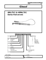
Page 1: ...ive VP Options Handle 40 Nutrunner Rotation Reversible 40 Non Reversible R Series X N C XX T L XX Built in Socket S Gear Train Designation P Specify Size Threaded Spindle T Output Drive Angle Terminat...

Page 2: ...re footing and proper posture in anticipation of a torquereaction The torque setting entered into the torque control monitor must not exceedmaximumtorquerangeoftool ortoolwillstallandnotshut off Opera...

Page 3: ...NSI B186 1 Safety Code for Portable Air Tools available from the American National Standards Institute Inc 11 West 42nd Street NewYork NY10036 This information is a compilation of general safety pract...

Page 4: ...mance use a 3 8 I D air hose no longer than 8 in length If additional length is required a 1 2 or larger hose should be connected to the 3 8 hose Being careful to avoid endangering adjacent personnel...

Page 5: ...he inlet bushing No 203355 and lift exhaust deflector far enough to unplug wire bundle No 203372 Un screw valve caps 3 No 203362 No 832207 and No 203360 Remove throttle lever No 867877 Remove throttle...

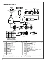
Page 6: ...r securely using the 5 8 16mm hex nut and 5 8 16mm deep socket Using a suitable driver through the hole in the top of the head drivethepinionbacktomakesureitisseatedproperlyinthe head M RIGHTANGLEHEAD...

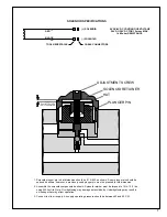
Page 7: ...015 020 as shown A new plunger pin should be spaced as shown however a previously used plunger pin must be pressed to this dimension 2 Assemble the solenoid components as shown Solenoid retainer must...

Page 8: ...ed Continue to turn adjustment screw clockwise Note Do not exceed 76 in lbs torque ADJUSTMENT SCREW 5 64 HEX WRENCH SOLENOID SEAT VALVE PLUNGER 6 While keeping throttle lever fully depressed and using...

Page 9: ...esistor Value in ohms of the torque monitor used The following is an example of a 40 series right angle tool with a 10M gear train angle head and a torque monitor with a 110 000 ohm calibration resist...

Page 10: ...ED SIGNAL RED RED SOLENOID CAMBION CONNECTORS BLACK BLACK ARMOR CABLE 35 40 SOLENOID CONTROL TOOL WIRING DIAGRAM S S T T U U V V WHITE WHITE WHITE WHITE YELLOW LED YELLOW LED COMMON GREEN LED RED LED...

Page 11: ...in Retainer Plug 3 8 Lock Pin Spring 3 8 Socket Lock Pin 3 8 1 4 x 3 8 O Ring 11 16 x 13 16 O Ring Pinion Ball Bearing Lock Pin Spring 1 4 Pinion Ball Ring Retainer 008 Spacer GreasePlug 004 Spacer An...

Page 12: ...3 32 Steel Ball Grease Fitting Lock Pin Spring O Ring 1 2 x 5 8 Pinion Ball Bearing PinionNeedleBearing PinionBearingRetainer Head Positioning Shim 008 DrivenGear SpindleBearingCap Head Positioning S...

Page 13: ...2 Sq Dr Socket Lock Pin 1 844013 SpringRetainer 1 844014 3 8 1 2 Sq Dr Spring 1 844016 3 8 Sq Dr Socket Lock Pin 1 847272 O Ring 5 8 x 3 4 1 864105 HousingNeedleBearing 1 867546 Housing Set Screw 1 4...

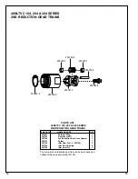
Page 14: ...Gear Bearing 6 203750 Idler Gear Pin 3 PART NO NAME OF PART QTY 40NLTVC 104 204 304 SERIES 2ND REDUCTION GEAR TRAINS PARTS LIST 40NLTVC 104 204 304 SERIES 2ND REDUCTION GEAR TRAINS 203453 6 203743 0 2...

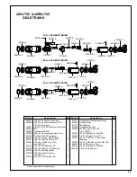
Page 15: ...Spider incl 203793 10 104 1st Red Gear Pin Part No Name of Part Qty Part No Name of Part Qty 1 1 1 1 1 1 1 3 3 3 3 3 1 1 3 TransducerBearingRetainerRing RetainerRing BallBearing TransducerBearing 20...

Page 16: ...ENOID NUTRUNNER PART NO NAME OF PART QTY PARTS LIST 40 SERIES MOTORS PART NO NAME OF PART QTY 203635 Rear Bearing Plate 1 203638 Cylinder 1 203703 10 104 20 204 Drive Shaft 1 203704 30 304 Drive Shaft...

Page 17: ...Bundle 19 Pin Reversing Valve Spacer Reversing Valve Part No Name of Part Qty Part No Name of Part Qty 1 1 1 1 1 1 1 4 1 1 1 1 1 1 1 1 1 1 1 1 1 1 1 1 1 1 1 1 1 1 1 1 1 1 1 1 1 3 2 1 1 2 2 1 1 2 2 1 1...

Page 18: ...ecurely 4 Tool equipped with the K or M head must have all components tightened Then the angle head must be loosened and shimmed to position angle head in relation ship to throttle lever Use wrench to...

Page 19: ...r case with another wrench 4 The P angle head has a spline for positioning the head to the throttle lever Once alignment is achieved the housing lock nut should be torqued to 20 ft lbs 27Nm Use wrench...

Page 20: ...20 670 Industrial Drive Lexington SC 29072 Phone 803 359 1200 Fax 803 359 2013...

Reviews: