background image

15

202875
202876

202877
202879
202888
202889
203702
203749
203781
203782

203783
203784
203785
203786

203793

1
1
1
1

3
1
1

3
3
3
1
1

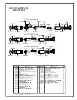
40NLTVC & 40RNLTVC

GEAR TRAINS

*  Parts not included in subassembly.

619017
844364
847147
847566
867866

867872
867902
867921

867922
869181
869182

 869584*

10 & 104 Transducer Gear Case
10 & 04 Transducer Ring Gear (45T)
10 & 104 Transducer
20, 204, 30 & 304 Transducer Ring Gear
(42T)
Transducer Roll Pin
20 & 204 Transducerized Gear Case
20, 204, 30 & 304 Transducer
10 & 104 1st Red. Gear Bearing
10 & 104 2nd Red. Gear (15T)
10 & 104 1st Red. Gear (15T)
(incl. 203749)
10 & 104 2nd Red Gear Pin
10 & 104 2nd Red. Gear Bearing
10 & 104 2nd Red. Spider
10 & 104 1st Red. Spider
(incl. 203793)
10 & 104 1st Red. Gear Pin

Part No.

Name of Part

Qty. Part No.

Name of Part

Qty.

1
1
1

1
1
1
1
3
3

3
3
3
1

1
3

Transducer Bearing Retainer Ring
Retainer Ring
Ball Bearing
Transducer Bearing
20 & 204 Idler Gear (18T)
(incl. 867921)
20 & 204 Spider (incl. 867922)
10 & 104 Rotor Pinion (15T)
20, 204, 30 & 304 1st Red. Gear
Bearing
20, 204, 30 & 304 1st Red. Gear Pin
30 & 304 1st Red. Gear
30 & 304 Spider (incl. 867922)
 & 104 Pinion Spacer

202876-9 

202875-1

847147-6

844364-0

-10 & -104 GEAR TRAINS

847566-7

619017-8

202877-7

202888-4

202889-2

847147-6

844364-0

867872-4

867922-7

867866-6

867921-9

-20 & -204 GEAR TRAINS

202879-3

847566-7

619017-8

203702-6

202888-4

202889-2

847147-6

844364-0

869182-6

867922-7

869181-8

867921-9

-30 & -304 GEAR TRAINS

202879-3

847566-7

619017-8

203702-6

202888-4

867902-9

869584-3

203781-0

203784-4

203783-6

203782-8

203793-5

203749-7

203785-1

203786-9

Summary of Contents for 40NLTVC Series

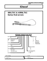
Page 1: ...ive VP Options Handle 40 Nutrunner Rotation Reversible 40 Non Reversible R Series X N C XX T L XX Built in Socket S Gear Train Designation P Specify Size Threaded Spindle T Output Drive Angle Terminat...

Page 2: ...re footing and proper posture in anticipation of a torquereaction The torque setting entered into the torque control monitor must not exceedmaximumtorquerangeoftool ortoolwillstallandnotshut off Opera...

Page 3: ...NSI B186 1 Safety Code for Portable Air Tools available from the American National Standards Institute Inc 11 West 42nd Street NewYork NY10036 This information is a compilation of general safety pract...

Page 4: ...mance use a 3 8 I D air hose no longer than 8 in length If additional length is required a 1 2 or larger hose should be connected to the 3 8 hose Being careful to avoid endangering adjacent personnel...

Page 5: ...he inlet bushing No 203355 and lift exhaust deflector far enough to unplug wire bundle No 203372 Un screw valve caps 3 No 203362 No 832207 and No 203360 Remove throttle lever No 867877 Remove throttle...

Page 6: ...r securely using the 5 8 16mm hex nut and 5 8 16mm deep socket Using a suitable driver through the hole in the top of the head drivethepinionbacktomakesureitisseatedproperlyinthe head M RIGHTANGLEHEAD...

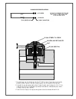
Page 7: ...015 020 as shown A new plunger pin should be spaced as shown however a previously used plunger pin must be pressed to this dimension 2 Assemble the solenoid components as shown Solenoid retainer must...

Page 8: ...ed Continue to turn adjustment screw clockwise Note Do not exceed 76 in lbs torque ADJUSTMENT SCREW 5 64 HEX WRENCH SOLENOID SEAT VALVE PLUNGER 6 While keeping throttle lever fully depressed and using...

Page 9: ...esistor Value in ohms of the torque monitor used The following is an example of a 40 series right angle tool with a 10M gear train angle head and a torque monitor with a 110 000 ohm calibration resist...

Page 10: ...ED SIGNAL RED RED SOLENOID CAMBION CONNECTORS BLACK BLACK ARMOR CABLE 35 40 SOLENOID CONTROL TOOL WIRING DIAGRAM S S T T U U V V WHITE WHITE WHITE WHITE YELLOW LED YELLOW LED COMMON GREEN LED RED LED...

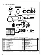
Page 11: ...in Retainer Plug 3 8 Lock Pin Spring 3 8 Socket Lock Pin 3 8 1 4 x 3 8 O Ring 11 16 x 13 16 O Ring Pinion Ball Bearing Lock Pin Spring 1 4 Pinion Ball Ring Retainer 008 Spacer GreasePlug 004 Spacer An...

Page 12: ...3 32 Steel Ball Grease Fitting Lock Pin Spring O Ring 1 2 x 5 8 Pinion Ball Bearing PinionNeedleBearing PinionBearingRetainer Head Positioning Shim 008 DrivenGear SpindleBearingCap Head Positioning S...

Page 13: ...2 Sq Dr Socket Lock Pin 1 844013 SpringRetainer 1 844014 3 8 1 2 Sq Dr Spring 1 844016 3 8 Sq Dr Socket Lock Pin 1 847272 O Ring 5 8 x 3 4 1 864105 HousingNeedleBearing 1 867546 Housing Set Screw 1 4...

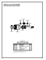
Page 14: ...Gear Bearing 6 203750 Idler Gear Pin 3 PART NO NAME OF PART QTY 40NLTVC 104 204 304 SERIES 2ND REDUCTION GEAR TRAINS PARTS LIST 40NLTVC 104 204 304 SERIES 2ND REDUCTION GEAR TRAINS 203453 6 203743 0 2...

Page 15: ...Spider incl 203793 10 104 1st Red Gear Pin Part No Name of Part Qty Part No Name of Part Qty 1 1 1 1 1 1 1 3 3 3 3 3 1 1 3 TransducerBearingRetainerRing RetainerRing BallBearing TransducerBearing 20...

Page 16: ...ENOID NUTRUNNER PART NO NAME OF PART QTY PARTS LIST 40 SERIES MOTORS PART NO NAME OF PART QTY 203635 Rear Bearing Plate 1 203638 Cylinder 1 203703 10 104 20 204 Drive Shaft 1 203704 30 304 Drive Shaft...

Page 17: ...Bundle 19 Pin Reversing Valve Spacer Reversing Valve Part No Name of Part Qty Part No Name of Part Qty 1 1 1 1 1 1 1 4 1 1 1 1 1 1 1 1 1 1 1 1 1 1 1 1 1 1 1 1 1 1 1 1 1 1 1 1 1 3 2 1 1 2 2 1 1 2 2 1 1...

Page 18: ...ecurely 4 Tool equipped with the K or M head must have all components tightened Then the angle head must be loosened and shimmed to position angle head in relation ship to throttle lever Use wrench to...

Page 19: ...r case with another wrench 4 The P angle head has a spline for positioning the head to the throttle lever Once alignment is achieved the housing lock nut should be torqued to 20 ft lbs 27Nm Use wrench...

Page 20: ...20 670 Industrial Drive Lexington SC 29072 Phone 803 359 1200 Fax 803 359 2013...

Reviews: