background image

12

201102
201103
201104
201214
202566
202567
202568
202569
202725
842517
842980
843589
847219
847710
847846

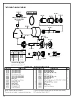
 "M" RIGHT ANGLE HEAD

*Number of spacers required is variable.
**Denotes parts not included in subassemblies listed below.

The complete "M" Right Angle Head can be purchased as a subassembly.
3/8" Square Drive Spindle — 861637

PARTS LIST —  "M" RIGHT ANGLE HEAD

PART NO.

PART NO.

NAME OF PART

NAME OF PART

QTY.

QTY.

863360
863564
863698
864076
864396
865723
867641
867642
867643

869034
869048
869049
869050
882629

10mm Conversion Kit
13mm Conversion Kit
15mm Conversion Kit
11mm Conversion Kit
10mm Flush Socket Spindle
13mm Flush Socket Spindle
15mm Flush Socket Spindle
Bearing Cap
11mm Flush Socket Spindle
Spindle Ball Bearing
3/32' Steel Ball
Grease Fitting
Lock Pin Spring
"O"-Ring 1/2" x 5/8"
Pinion Ball Bearing

Pinion Needle Bearing
Pinion Bearing Retainer
Head Positioning Shim (.008')
Driven Gear
Spindle Bearing Cap
Head Positioning Shim (.004')
Lock Pin Retainer Plug
Socket Lock Pin
3/8" Sq. Dr. Spindle (incl. 847219, 867641, 867642)
Angle Head Adapter
Right Angle Head (incl. 843589)
Pinion
Bearing Spacer
Spindle Needle Bearing

1
1
1
1
1
1
1
1
1
1

30

1
1
1
1

1
1

*

1
1

*

1
1

1
1
1
1
1
1

863564

869050

863360

847846

869048

869049

882629

864076

842517

847710

864396

867641

869034

ANGLE HEAD ADAPTER

Stall Tools Only

843589

867642

847219

867643

842980

202569

863698      .008"
865723      .004"

     FLUSH SOCKET SPINDLE
SIZE     SPINDLE   CONVERSION
            PART NO.  KIT* PART NO.
10mm  202566-6         201102
11mm  202725-8         201214
13mm  202567-4         201103
14mm  ------------          ------------
15mm  202568-2         201104

*Conversion kit contains all parts 
needed to convert a "M" right angle 
head to flush socket operation. 

3/8-24 Drill Spindle

869051

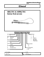
Summary of Contents for 40NLTVC Series

Page 1: ...ive VP Options Handle 40 Nutrunner Rotation Reversible 40 Non Reversible R Series X N C XX T L XX Built in Socket S Gear Train Designation P Specify Size Threaded Spindle T Output Drive Angle Terminat...

Page 2: ...re footing and proper posture in anticipation of a torquereaction The torque setting entered into the torque control monitor must not exceedmaximumtorquerangeoftool ortoolwillstallandnotshut off Opera...

Page 3: ...NSI B186 1 Safety Code for Portable Air Tools available from the American National Standards Institute Inc 11 West 42nd Street NewYork NY10036 This information is a compilation of general safety pract...

Page 4: ...mance use a 3 8 I D air hose no longer than 8 in length If additional length is required a 1 2 or larger hose should be connected to the 3 8 hose Being careful to avoid endangering adjacent personnel...

Page 5: ...he inlet bushing No 203355 and lift exhaust deflector far enough to unplug wire bundle No 203372 Un screw valve caps 3 No 203362 No 832207 and No 203360 Remove throttle lever No 867877 Remove throttle...

Page 6: ...r securely using the 5 8 16mm hex nut and 5 8 16mm deep socket Using a suitable driver through the hole in the top of the head drivethepinionbacktomakesureitisseatedproperlyinthe head M RIGHTANGLEHEAD...

Page 7: ...015 020 as shown A new plunger pin should be spaced as shown however a previously used plunger pin must be pressed to this dimension 2 Assemble the solenoid components as shown Solenoid retainer must...

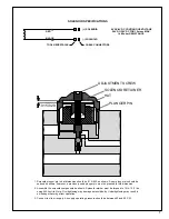
Page 8: ...ed Continue to turn adjustment screw clockwise Note Do not exceed 76 in lbs torque ADJUSTMENT SCREW 5 64 HEX WRENCH SOLENOID SEAT VALVE PLUNGER 6 While keeping throttle lever fully depressed and using...

Page 9: ...esistor Value in ohms of the torque monitor used The following is an example of a 40 series right angle tool with a 10M gear train angle head and a torque monitor with a 110 000 ohm calibration resist...

Page 10: ...ED SIGNAL RED RED SOLENOID CAMBION CONNECTORS BLACK BLACK ARMOR CABLE 35 40 SOLENOID CONTROL TOOL WIRING DIAGRAM S S T T U U V V WHITE WHITE WHITE WHITE YELLOW LED YELLOW LED COMMON GREEN LED RED LED...

Page 11: ...in Retainer Plug 3 8 Lock Pin Spring 3 8 Socket Lock Pin 3 8 1 4 x 3 8 O Ring 11 16 x 13 16 O Ring Pinion Ball Bearing Lock Pin Spring 1 4 Pinion Ball Ring Retainer 008 Spacer GreasePlug 004 Spacer An...

Page 12: ...3 32 Steel Ball Grease Fitting Lock Pin Spring O Ring 1 2 x 5 8 Pinion Ball Bearing PinionNeedleBearing PinionBearingRetainer Head Positioning Shim 008 DrivenGear SpindleBearingCap Head Positioning S...

Page 13: ...2 Sq Dr Socket Lock Pin 1 844013 SpringRetainer 1 844014 3 8 1 2 Sq Dr Spring 1 844016 3 8 Sq Dr Socket Lock Pin 1 847272 O Ring 5 8 x 3 4 1 864105 HousingNeedleBearing 1 867546 Housing Set Screw 1 4...

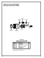
Page 14: ...Gear Bearing 6 203750 Idler Gear Pin 3 PART NO NAME OF PART QTY 40NLTVC 104 204 304 SERIES 2ND REDUCTION GEAR TRAINS PARTS LIST 40NLTVC 104 204 304 SERIES 2ND REDUCTION GEAR TRAINS 203453 6 203743 0 2...

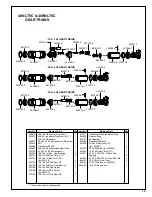
Page 15: ...Spider incl 203793 10 104 1st Red Gear Pin Part No Name of Part Qty Part No Name of Part Qty 1 1 1 1 1 1 1 3 3 3 3 3 1 1 3 TransducerBearingRetainerRing RetainerRing BallBearing TransducerBearing 20...

Page 16: ...ENOID NUTRUNNER PART NO NAME OF PART QTY PARTS LIST 40 SERIES MOTORS PART NO NAME OF PART QTY 203635 Rear Bearing Plate 1 203638 Cylinder 1 203703 10 104 20 204 Drive Shaft 1 203704 30 304 Drive Shaft...

Page 17: ...Bundle 19 Pin Reversing Valve Spacer Reversing Valve Part No Name of Part Qty Part No Name of Part Qty 1 1 1 1 1 1 1 4 1 1 1 1 1 1 1 1 1 1 1 1 1 1 1 1 1 1 1 1 1 1 1 1 1 1 1 1 1 3 2 1 1 2 2 1 1 2 2 1 1...

Page 18: ...ecurely 4 Tool equipped with the K or M head must have all components tightened Then the angle head must be loosened and shimmed to position angle head in relation ship to throttle lever Use wrench to...

Page 19: ...r case with another wrench 4 The P angle head has a spline for positioning the head to the throttle lever Once alignment is achieved the housing lock nut should be torqued to 20 ft lbs 27Nm Use wrench...

Page 20: ...20 670 Industrial Drive Lexington SC 29072 Phone 803 359 1200 Fax 803 359 2013...

Reviews: