


Chapter 2 — Burner Operation and Control
2-18
Part No. 750-184
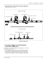
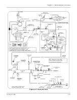
L. OIL FUEL FLOW - HEAVY OIL
The oil fuel flow and circulating system is shown in schematic
diagram form in Figure 2-17. The pertinent controls are called out
and the oil flow is indicated by arrows.
Fuel oil is delivered into the system by the fuel oil supply pump
which delivers part of its discharge to the oil heater. The remainder
of the fuel oil returns to the oil storage tank through a fuel oil relief
valve and oil return line.
The combination electric and steam oil preheater is controlled by
thermostats. The electric oil heater thermostat energizes the electric
heater, which is provided to supply heated oil on cold starts. The
steam heater thermostat controls operation of the steam solenoid
valve to permit a flow of steam to the heater when steam is
available.
A hot water boiler is equipped to heat the oil with hot water from
the boiler, unless other preheating equipment is utilized. The
electric heater, which is housed separately, is sized to provide
heated oil on a cold start. The hot water thermostat controls the
operation of a pump that supplies hot water to the oil heater when
hot water is available.
The heated oil flows through a fuel oil strainer to prevent any foreign
matter from entering the control valves and nozzle.
The fuel oil controller contains, in a single unit, the necessary
valves, regulators and gauges to regulate the pressure and flow of
oil to the burner.
The program relay energizes or deenergizes the solenoid oil valve to
permit or cut off oil flow to the burner. The oil solenoid is closed
when deenergized. It cannot be opened (energized) unless the
combustion air proving switch, the atomizing air proving switch,
and the low oil-temperature and any pressure switches are closed.
They are satisfied, respectively, by sufficient combustion air
pressure from the forced draft fan, pressurized air from the air pump
and sufficient oil temperature and pressure.
Oil flow to the burner is controlled by the movement of the metering
stem of the oil metering valve, which varies the flow to meet load
demands. The metering valve and the air damper are controlled
simultaneously at all times by the modulating motor to proportion
combustion air and fuel for changes in load demand.
Oil is purged from the burner gun upon each burner shutdown. The
air purge solenoid valve opens as the fuel valve closes, diverting
atomizing air through the oil line. The air assures a clean nozzle and
line for subsequent restart.
Summary of Contents for CB Ohio Special 100 HP
Page 2: ...ii ...
Page 8: ...viii ...
Page 42: ...Chapter 2 Burner Operation and Control 2 22 Part No 750 184 ...
Page 116: ...Chapter 6 Adjustment Procedures 6 28 Part No 750 184 ...
Page 126: ...Chapter 8 Inspection and Maintenance 8 6 Part No 750 184 ...
Page 153: ...Chapter 9 Parts Part No 750 184 9 3 Insulated Front Head Model CB LE ...
Page 154: ...Chapter 9 Parts 9 4 Part No 750 184 Insulated Front Head Interior Model CB LE ...
Page 155: ...Chapter 9 Parts Part No 750 184 9 5 Insulated Inner Door Model CB OS ...
Page 156: ...Chapter 9 Parts 9 6 Part No 750 184 Insulated Rear Head CB LE ...
Page 157: ...Chapter 9 Parts Part No 750 184 9 7 Insulated Rear Head CB LE ...
Page 158: ...Chapter 9 Parts 9 8 Part No 750 184 Insulated Rear Head CB OS ...
Page 159: ...Chapter 9 Parts Part No 750 184 9 9 Dry Oven Model CB LE ...
Page 161: ...Chapter 9 Parts Part No 750 184 9 11 Motor Impeller Model CB LE ...
Page 162: ...Chapter 9 Parts 9 12 Part No 750 184 Front Head Linkage ...
Page 170: ...Chapter 9 Parts 9 20 Part No 750 184 Control Cabinet Hawk ICS ...
Page 171: ...Chapter 9 Parts Part No 750 184 9 21 Control Panel Standard ...
Page 172: ...Chapter 9 Parts 9 22 Part No 750 184 Entrance Box ...
Page 173: ...Chapter 9 Parts Part No 750 184 9 23 Front Head Electrical CB LE ...
Page 174: ...Chapter 9 Parts 9 24 Part No 750 184 Front Head Electrical CB LE ...
Page 175: ...Chapter 9 Parts Part No 750 184 9 25 Front Head Electrical CB OS ...
Page 176: ...Chapter 9 Parts 9 26 Part No 750 184 Front Head Electrical CB OS ...
Page 179: ...Chapter 9 Parts Part No 750 184 9 29 Heavy Oil Piping 60 Steam CB LE ...
Page 180: ...Chapter 9 Parts 9 30 Part No 750 184 Heavy Oil Piping 60 Steam CB LE SEE TABLE NEXT PAGE ...
Page 181: ...Chapter 9 Parts Part No 750 184 9 31 Common Oil Parts Heavy Oil ...
Page 182: ...Chapter 9 Parts 9 32 Part No 750 184 Side Mounted Air Compressor Piping ...
Page 183: ...Chapter 9 Parts Part No 750 184 9 33 Air Compressor Piping CB OS ...
Page 185: ...Chapter 9 Parts Part No 750 184 9 35 Light Oil Piping ...
Page 186: ...Chapter 9 Parts 9 36 Part No 750 184 Light Oil Air Piping Front Head ...
Page 187: ...Chapter 9 Parts Part No 750 184 9 37 Light Oil Air Piping Front Head PAGE 9 31 ...
Page 191: ...Chapter 9 Parts Part No 750 184 9 41 Gas Train 125 150 HP ...
Page 193: ...Chapter 9 Parts Part No 750 184 9 43 Gas Train 200 HP ...
Page 195: ...Chapter 9 Parts Part No 750 184 9 45 Steam Pressure Controls ...
Page 196: ...Chapter 9 Parts 9 46 Part No 750 184 Hot Water Temperature Controls ...
Page 197: ...Chapter 9 Parts Part No 750 184 9 47 Water Column ...
Page 198: ...Chapter 9 Parts 9 48 Part No 750 184 Water Column ...
Page 199: ...Chapter 9 Parts Part No 750 184 9 49 Fireside Gaskets CB LE ...
Page 200: ...Chapter 9 Parts 9 50 Part No 750 184 Fireside Gaskets CB OS ...


