


Chapter 2 — Burner Operation and Control
2-2
Part No. 750-184
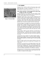
A. THE BURNER
The gas burner is of the non-premix orifice type, using a spark
ignited gas pilot. The pilot is of the interrupted type and is
extinguished after main flame is established.
The oil burner is of the low pressure, air atomizing (nozzle) type.
Note: A Series 100 boiler is usually equipped with a light oil pilot,
although a gas pilot is also available.
Burners equipped to burn oil and gas (combination burners) include
equipment for each fuel. Since the burner uses only one type of fuel
at a time, a gas/oil selector switch is incorporated.
Regardless of which fuel is used, the burner operates with full
modulation (within its rated operating range). The burner returns to
minimum firing position for ignition. High-pressure boilers (above
15 psi) can be wired for both low-pressure and high-pressure
modulation, which enables the boiler to operate at lower pressure
during off-load hours, but at a somewhat reduced steam output,
dependent upon lower steam pressure and steam nozzle sizing.
The flame safeguard and program relay include a flame detector to
supervise both oil and gas flames, and to shut the burner down in
the event of loss of flame. The programming portion of the control
provides a pre-purging period, proving of the pilot and main flame,
and a period of continued blower operation to postpurge the boiler
of all unburned fuel vapor. Other safety controls shut down the
burner under low-water conditions, excess steam pressure, or water
temperature.
Safety interlock controls include combustion and atomizing air
proving switches and, depending upon the fuel and insurance
carrier requirements, controls that prove the presence of adequate
fuel pressure, plus temperature proving controls when heated fuel
oil is used.
The sequence of burner operation from startup through shutdown is
governed by the program relay in conjunction with the operating,
limit and interlock devices. The devices are wired into the circuitry
to provide safe operation and protect against incorrect operating
techniques.
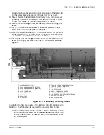
All CB-LE boilers have the burner assembly attached to the front
head. The entire head may be swung open for inspection and
maintenance.
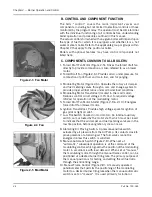
Combustion air is provided by a centrifugal blower located in the
front head. Combustion air delivery to the burner is under the
control of the modulating motor. The motor also regulates the flow
of fuel through a linkage system connected to the gas butterfly valve
and/or oil through a cam-operated metering valve. Fuel input and
air are thus properly proportioned for most efficient combustion.
Filtered primary air for atomizing fuel oil is furnished independently
of combustion air by an air pump. The 60” CB-LE boiler uses a side-
mounted air compressor for atomizing air.
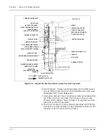
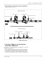
Figure 2-1 Burner drawer
Summary of Contents for CB Ohio Special 100 HP
Page 2: ...ii ...
Page 8: ...viii ...
Page 42: ...Chapter 2 Burner Operation and Control 2 22 Part No 750 184 ...
Page 116: ...Chapter 6 Adjustment Procedures 6 28 Part No 750 184 ...
Page 126: ...Chapter 8 Inspection and Maintenance 8 6 Part No 750 184 ...
Page 153: ...Chapter 9 Parts Part No 750 184 9 3 Insulated Front Head Model CB LE ...
Page 154: ...Chapter 9 Parts 9 4 Part No 750 184 Insulated Front Head Interior Model CB LE ...
Page 155: ...Chapter 9 Parts Part No 750 184 9 5 Insulated Inner Door Model CB OS ...
Page 156: ...Chapter 9 Parts 9 6 Part No 750 184 Insulated Rear Head CB LE ...
Page 157: ...Chapter 9 Parts Part No 750 184 9 7 Insulated Rear Head CB LE ...
Page 158: ...Chapter 9 Parts 9 8 Part No 750 184 Insulated Rear Head CB OS ...
Page 159: ...Chapter 9 Parts Part No 750 184 9 9 Dry Oven Model CB LE ...
Page 161: ...Chapter 9 Parts Part No 750 184 9 11 Motor Impeller Model CB LE ...
Page 162: ...Chapter 9 Parts 9 12 Part No 750 184 Front Head Linkage ...
Page 170: ...Chapter 9 Parts 9 20 Part No 750 184 Control Cabinet Hawk ICS ...
Page 171: ...Chapter 9 Parts Part No 750 184 9 21 Control Panel Standard ...
Page 172: ...Chapter 9 Parts 9 22 Part No 750 184 Entrance Box ...
Page 173: ...Chapter 9 Parts Part No 750 184 9 23 Front Head Electrical CB LE ...
Page 174: ...Chapter 9 Parts 9 24 Part No 750 184 Front Head Electrical CB LE ...
Page 175: ...Chapter 9 Parts Part No 750 184 9 25 Front Head Electrical CB OS ...
Page 176: ...Chapter 9 Parts 9 26 Part No 750 184 Front Head Electrical CB OS ...
Page 179: ...Chapter 9 Parts Part No 750 184 9 29 Heavy Oil Piping 60 Steam CB LE ...
Page 180: ...Chapter 9 Parts 9 30 Part No 750 184 Heavy Oil Piping 60 Steam CB LE SEE TABLE NEXT PAGE ...
Page 181: ...Chapter 9 Parts Part No 750 184 9 31 Common Oil Parts Heavy Oil ...
Page 182: ...Chapter 9 Parts 9 32 Part No 750 184 Side Mounted Air Compressor Piping ...
Page 183: ...Chapter 9 Parts Part No 750 184 9 33 Air Compressor Piping CB OS ...
Page 185: ...Chapter 9 Parts Part No 750 184 9 35 Light Oil Piping ...
Page 186: ...Chapter 9 Parts 9 36 Part No 750 184 Light Oil Air Piping Front Head ...
Page 187: ...Chapter 9 Parts Part No 750 184 9 37 Light Oil Air Piping Front Head PAGE 9 31 ...
Page 191: ...Chapter 9 Parts Part No 750 184 9 41 Gas Train 125 150 HP ...
Page 193: ...Chapter 9 Parts Part No 750 184 9 43 Gas Train 200 HP ...
Page 195: ...Chapter 9 Parts Part No 750 184 9 45 Steam Pressure Controls ...
Page 196: ...Chapter 9 Parts 9 46 Part No 750 184 Hot Water Temperature Controls ...
Page 197: ...Chapter 9 Parts Part No 750 184 9 47 Water Column ...
Page 198: ...Chapter 9 Parts 9 48 Part No 750 184 Water Column ...
Page 199: ...Chapter 9 Parts Part No 750 184 9 49 Fireside Gaskets CB LE ...
Page 200: ...Chapter 9 Parts 9 50 Part No 750 184 Fireside Gaskets CB OS ...


