


Chapter 6 — Adjustment Procedures
6-16
Part No. 750-184
Pressure
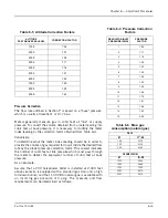
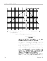
Correction for the 2,000 feet altitude must be made since altitude
has a bearing on the net regulated gas pressure. The standard gas
train requires 15.5" WC gas pressure at sea level (Table 6-1). Table
6-2 indicates a correction factor of 1.07 for 2,000 feet. Multiplying
the results in a calculated net regulated gas requirement of
approximately 16.6" WC. This is the initial pressure to which the
regulator should be adjusted. Slight additional adjustment can be
made later, if necessary, to obtain the gas input needed for burner
rating.
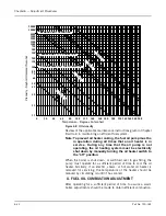
Flow
Since the gas flow rate is based on standard conditions of flow,
correction must be made for the supply pressure through the meter
of 3 psig. Determine the flow rate by dividing the Btu content of the
gas into the burner input and “correct” this answer by applying the
correction factor for 3 psig (Table 6-4).
Btu/hr Input = CFH (Cubic feet/hour)
Btu/cu-ft
OR
8,369,000
= 8,369 CFH (At 14.7 Ib-atmospheric base 1,000 pressure)
THEN
8,369 = 7,092 CFH
1.18
This is the CFH (at line pressure) that must pass through the meter
so that the equivalent full input requirement of 25,100 CFH (at
base pressure) will be delivered.
Checking Gas Flow
Your gas supplier can generally furnish a gas meter flow chart from
which gas flow can be determined. After a short observation period,
the information aids in adjusting the regulator to increase or
decrease flow as required to obtain rated output.
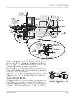
Final adjustment of the gas fuel is carried out by means of the
adjusting screws in the gas modulating cam, while performing a
combustion efficiency analysis. See Section Q for details.
Note: The information given in this section is for all practical
purposes sufficient to set and adjust controls for gas
input. Your gas supplier can, if necessary, furnish exact
correction factors that take into consideration Btu
content, exact base pressure, specific gravity,
temperature, etc., of the gas used.
Q. GAS FUEL COMBUSTION ADJUSTMENT
After operating for a sufficient period of time to assure a warm
boiler, adjustments should be made to obtain efficient combustion.
Summary of Contents for CB Ohio Special 100 HP
Page 2: ...ii ...
Page 8: ...viii ...
Page 42: ...Chapter 2 Burner Operation and Control 2 22 Part No 750 184 ...
Page 116: ...Chapter 6 Adjustment Procedures 6 28 Part No 750 184 ...
Page 126: ...Chapter 8 Inspection and Maintenance 8 6 Part No 750 184 ...
Page 153: ...Chapter 9 Parts Part No 750 184 9 3 Insulated Front Head Model CB LE ...
Page 154: ...Chapter 9 Parts 9 4 Part No 750 184 Insulated Front Head Interior Model CB LE ...
Page 155: ...Chapter 9 Parts Part No 750 184 9 5 Insulated Inner Door Model CB OS ...
Page 156: ...Chapter 9 Parts 9 6 Part No 750 184 Insulated Rear Head CB LE ...
Page 157: ...Chapter 9 Parts Part No 750 184 9 7 Insulated Rear Head CB LE ...
Page 158: ...Chapter 9 Parts 9 8 Part No 750 184 Insulated Rear Head CB OS ...
Page 159: ...Chapter 9 Parts Part No 750 184 9 9 Dry Oven Model CB LE ...
Page 161: ...Chapter 9 Parts Part No 750 184 9 11 Motor Impeller Model CB LE ...
Page 162: ...Chapter 9 Parts 9 12 Part No 750 184 Front Head Linkage ...
Page 170: ...Chapter 9 Parts 9 20 Part No 750 184 Control Cabinet Hawk ICS ...
Page 171: ...Chapter 9 Parts Part No 750 184 9 21 Control Panel Standard ...
Page 172: ...Chapter 9 Parts 9 22 Part No 750 184 Entrance Box ...
Page 173: ...Chapter 9 Parts Part No 750 184 9 23 Front Head Electrical CB LE ...
Page 174: ...Chapter 9 Parts 9 24 Part No 750 184 Front Head Electrical CB LE ...
Page 175: ...Chapter 9 Parts Part No 750 184 9 25 Front Head Electrical CB OS ...
Page 176: ...Chapter 9 Parts 9 26 Part No 750 184 Front Head Electrical CB OS ...
Page 179: ...Chapter 9 Parts Part No 750 184 9 29 Heavy Oil Piping 60 Steam CB LE ...
Page 180: ...Chapter 9 Parts 9 30 Part No 750 184 Heavy Oil Piping 60 Steam CB LE SEE TABLE NEXT PAGE ...
Page 181: ...Chapter 9 Parts Part No 750 184 9 31 Common Oil Parts Heavy Oil ...
Page 182: ...Chapter 9 Parts 9 32 Part No 750 184 Side Mounted Air Compressor Piping ...
Page 183: ...Chapter 9 Parts Part No 750 184 9 33 Air Compressor Piping CB OS ...
Page 185: ...Chapter 9 Parts Part No 750 184 9 35 Light Oil Piping ...
Page 186: ...Chapter 9 Parts 9 36 Part No 750 184 Light Oil Air Piping Front Head ...
Page 187: ...Chapter 9 Parts Part No 750 184 9 37 Light Oil Air Piping Front Head PAGE 9 31 ...
Page 191: ...Chapter 9 Parts Part No 750 184 9 41 Gas Train 125 150 HP ...
Page 193: ...Chapter 9 Parts Part No 750 184 9 43 Gas Train 200 HP ...
Page 195: ...Chapter 9 Parts Part No 750 184 9 45 Steam Pressure Controls ...
Page 196: ...Chapter 9 Parts 9 46 Part No 750 184 Hot Water Temperature Controls ...
Page 197: ...Chapter 9 Parts Part No 750 184 9 47 Water Column ...
Page 198: ...Chapter 9 Parts 9 48 Part No 750 184 Water Column ...
Page 199: ...Chapter 9 Parts Part No 750 184 9 49 Fireside Gaskets CB LE ...
Page 200: ...Chapter 9 Parts 9 50 Part No 750 184 Fireside Gaskets CB OS ...


