background image

Direct: 763.476.6866 • National: 800.422.2537 • www.SeeClearfield.com • [email protected] 

10

YOURx Flex Box

Installation Manual 

 _________________________________________________________

Manual 019209 REV F - Jan 2019

Drop wheels easily deploy by extending the wheel from the mounting 

cradle, pulling the fiber through the microduct, and then assembling the 

pulled connector.

Characteristic

Specification

Material

Black Thermoplastic

Fiber

200 Feet of FieldShield StrongFiber

Connectors

Pullable SC/APC to Standard SC/APC

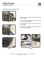
1.  Mount Drop Wheel cradle into appropriate mounting holes (previous page), 

mounting the block of Drop Wheels with the fiber termination ports oriented at 

the top of the Drop Wheel cradle as shown in (

Figure 1

).


Note:


Fiber peels off to the back of the wheel

.


2.  Pull/extend desired wheel forward (

Figure 1

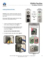
), carefully remove tape holding 

the fiber in place (

Figure 2

).

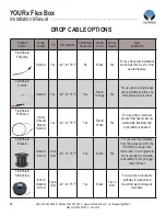
3.  Loop a half hitch knot around the connector at the first notch in the crimp tube, 

tie the microduct pull string to the connector pulling eye (

Figure 3

).


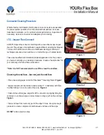
4. 

Feed the connector into the microduct, and with the drop wheel extended,  

carefully pull the fiber through the microduct (

Figure 4

).


Figure 1

Figure 2

Figure 3

Figure 4

Summary of Contents for YOURx Flex Box

Page 1: ...YOURx Flex Box Installation Manual _______________________________________________________ Manual 019209 REV F Jan 2019 ...

Page 2: ...commended Tools 3 Parts List 4 Components Aggregator Plates 5 Ship along Items 6 Using the Flex Box with Drop Wheels Max 16 8 Using the Flex Box Clearview Blue Cassette Up to 24 ports 12 Using the Aggregator Plates 15 Using the COMBO Aggregator Plates 16 Installing Microduct into Aggregator Plate 17 Installing Additional FlexPorts 18 Connector Cleaning Procedure 20 Standard Warranty 23 Proprietary...

Page 3: ...r plate and they are ready to pull fiber Slack storage is provided for both incoming and outgoing fiber in separate areas to reduce service interruptions when turning up additional subscribers The drop wheel feature accommodates up to 16 individ ual drop wheel assemblies with each drop wheel supporting up to 200ft of FieldShield StrongFiber storage The SmartRoute Plate can also be mounted in the F...

Page 4: ... 4 YOURx Flex Box Installation Manual __________________________________________________________ Manual 019209 REV F Jan 2019 Find No Tool Image 001 Rotary Cutter 002 Flat Cutter 003 Deburring Tool 004 Phillips Screwdriver 005 Pliers 006 Optical End Face Cleaning kit Recommended Tools ...

Page 5: ...ity Two cassettes 24 ports up to 16 in drop wheel SmartRoute 24 port Connectivity Types Clearview Blue Drop Wheel SmartRoute Plate Aggregator Plate Duct Plate 24 10 6mm and 2 14 10mm Microduct Combo Plate 24 10 6mm and Conduit Drop Wheel Fiber type FieldShield StrongFiber Drop Wheel Connector Pullable SC APC to Standard SC APC Drop Wheel Cable Length 200 feet Drop Wheel Material Black Thermoplasti...

Page 6: ... the plate ie additional FlexPorts or the addition of sealcons or conduit fittings 5 DUCT Plate Supports up to 2 14 10mm and 24 10 6mm microducts 6 PON Plate Supports 1 2 sealcon and 32 10 6mm microducts 7 BLANK Plate Can support up to a 2 inch conduit fitting Drill points added for easy drilling Slide in aggregator plates support multiple cable entries individual fiber cables conduit and microduc...

Page 7: ...l Direct 763 476 6866 National 800 422 2537 www SeeClearfield com techsupport clfd net Manual 019209 REV F Jan 2019 Ship along Items 8 9 8 Qty 5 Adhesive backed Fiber Management blocks w Velcro 9 Qty 4 Fiber management radius limiters with mounting screws 10 Qty 2 Threaded rod with nylon nuts 10 ...

Page 8: ...design which can be configured in the following ways 1 With the use of up to 2 Cassettes 24 ports Figure 1 OR 2 The drop wheel feature which accommodates up to 16 individual drop wheel assemblies with each drop wheel supporting up to 200ft of FieldShield StrongFiber storage Available in 4 wheel increments mounting screws included 4 count 8 count Figure 2 12 count 16 count Either choice allows for ...

Page 9: ...6866 National 800 422 2537 www SeeClearfield com techsupport clfd net Manual 019209 REV F Jan 2019 Using the Flex Box with Drop Wheels Max 16 Secure the drop wheel cradles with the provided screws following the provided hole diagram NOTE In earthquake regions the drop wheel cradle requires three screws per side ...

Page 10: ...PC to Standard SC APC 1 Mount Drop Wheel cradle into appropriate mounting holes previous page mounting the block of Drop Wheels with the fiber termination ports oriented at the top of the Drop Wheel cradle as shown in Figure 1 Note Fiber peels off to the back of the wheel 2 Pull extend desired wheel forward Figure 1 carefully remove tape holding the fiber in place Figure 2 3 Loop a half hitch knot...

Page 11: ...rly lock into place Figure 1 Step 3 Rotate counter clockwise 45 degrees to realign the inner housing and connector and push the inner housing onto the connector until it snaps into place Figure 3 Step 2 Align the black mark on the inner housing with the black line on the connector then rotate the inner housing 45 degrees to offset the lock Figure 2 and slide the inner housing half way over the con...

Page 12: ...rd connector from the center of the Drop Wheel through the access slot on the side of the Drop Wheel to the appropriate port on Drop Wheel Figure 7 Note Additional slack can be stored in the connector access slot in the middle of the drop wheel 7 Reinsert the drop wheel into the mounting bracket Make sure that the slide is properly aligned when reinserting the drop wheel Figure 8 Figure 7 Addition...

Page 13: ...19 Using the Flex Box Clearview Blue Cassette Up to 24 ports Figure 1 Figure 2 Fiber management is provided for both incoming and outgoing fiber in separate areas to reduce service interruptions when turning up additional subscribers 1 Place all 4 of the fiber management radius limiters onto the Flex Box in the designated holes as shown in Figure 1 2 Place the 5 fiber management blocks as shown in...

Page 14: ...se of wall box Figure 3 4 Slide cassettes onto threaded rods utilizing the holes in side rail of cassettes and place nylon nuts to secure Figure 4 Note If configuration includes In Cassette Splicing follow procedures outlined in Clearview Blue Cassette Manual for preparing and splicing then complete STEP 4 above 5 If needed up to 40 feet of 3mm jacket incoming fiber can be stored within the fiber ...

Page 15: ...ional 800 422 2537 www SeeClearfield com techsupport clfd net Manual 019209 REV F Jan 2019 Figure 6 Figure 7 1 Place screw hook into a convenient location hole for tying off pullstring when waiting to pull fiber Figure 6 2 Flex Box is now ready to accept fiber Figure 7 Note Cassette can be mounted in either direction or ...

Page 16: ...s secure plate to box as shown Figure 2 3 For OUTDOOR APPLICATIONS apply silicon bead onto aggregator plate before sliding into groove The Duct Plate Figure 3 with 2 14 10mm and 24 10 6mm ports arrives from the factory with 1 14 10mm FlexPort and the appropriate number of 10 6mm FlexPorts matching port count These FlexPorts will be marked on the opposite side tabs with a black X indicating that th...

Page 17: ...an 2019 Figure 2 Figure 3 Place conduit fitting Figure 2 or Sealcon Figure 3 Additional FlexPorts can be added in the field utilizing the 9 match points Figure 4 Using the COMBO Aggregator Plates Figure 1 COMBO Plate Figure 1 with 24 10 6mm ports Also has the ability to have field installed FlexPort sealcons or conduit fittings Note Max hole size is 2 3 8 to keep integrity of the plate intact Figu...

Page 18: ...iers snap off tab of desired FlexPort marked with black X Figure 1 2 De burr port using the de burring tool as shown or snips knife to remove any sharp edges Figure 2 3 Push pull string through port tie off to the screw hook previously placed Figure 3 4 Properly prepare microduct flush cut and de burr then insert duct into FlexPort until snug Figure 4 Installing Microduct into Aggregator Plate Fig...

Page 19: ...r a smooth transition without damaging the fiber as it enters the port Figure 2 Note MUST BE FULLY DE BURRED FOR MPO 3 Following the diagram place parts as shown Figure 3 FlexPorts are factory installed into aggregator plates that come from the factory based on the port count specified at time of order When needed FlexPorts can be added in the field to allow the terminal to accept additional micro...

Page 20: ... For use when a single pass and restorable solution at a competitive price is ideal FieldShield FLEXdrop Indoor Plenum Rated Outdoor Yes 40 to 176 F Yes Black White Yes For use when a premium product that has maximum workability flexibility and restorability is desired FieldShield Classic Outdoor in Duct Yes in Duct 40 to 176 F Yes Black Yes For use when the distance from the access point to the S...

Page 21: ...techniques ensures a clean end face no matter the type of contamination These are Clearfield recommended products application Use the product you feel will complete your cleaning procedures Create a best practice for your company and follow those procedures Note It is NOT recommended to use IPA to clean the end face Cleaning the end face but not just the end face Place one wiping paper on QbE 2 Fi...

Page 22: ...cle around 2 3 times and remove Turn swab to dry side and repeat Figure 5 Cleaning the mate through a bulkhead adapter AND the adapter itself Lightly moisten the fiber optic swab 2 5mm 38542F or 1 25mm 38040 by spotting a small amount about 1 of Electro Wash PX or Elec tro Wash MX pen onto the QBE 2 Hold the tip of the swab onto the wetted area and hold for a count of 1 2 3 4 5 Insert the swab int...

Page 23: ...the container or end face Angle is correct when no drag is left on the end face Figure 2 Male Connector Lightly moisten the fiber optic swab CC505F like above moistening 1 side Place swab wet side down at one end of connector end face and draw across in a diagonal sweep ie from fiber 1 up and across to fiber 12 Turn swab over to dry and draw back from fiber 12 to fiber 1 Figure 3 BEFORE cleaning a...

Page 24: ... Clearfield Inc shall constitute the exclusive sole remedy for a breach of this limited warranty Clearfield shall not be liable under any circumstances for any special consequential incidental punitive or exemplary damages arising out of or in any way connected with the product or with agreement to sell product to buyer including but not limited to damages for lost profits loss of use or for any d...

Page 25: ...ied Every effort has been made to keep the information contained in this document current and accurate as of the date of publication or revision However no guarantee is given or implied that the document is error free or that it is accurate with regard to any specification Technical Support Clearfield Inc can be contacted for any issues that arise with the supplied product If you need to return th...

Reviews: