FieldSmart
®
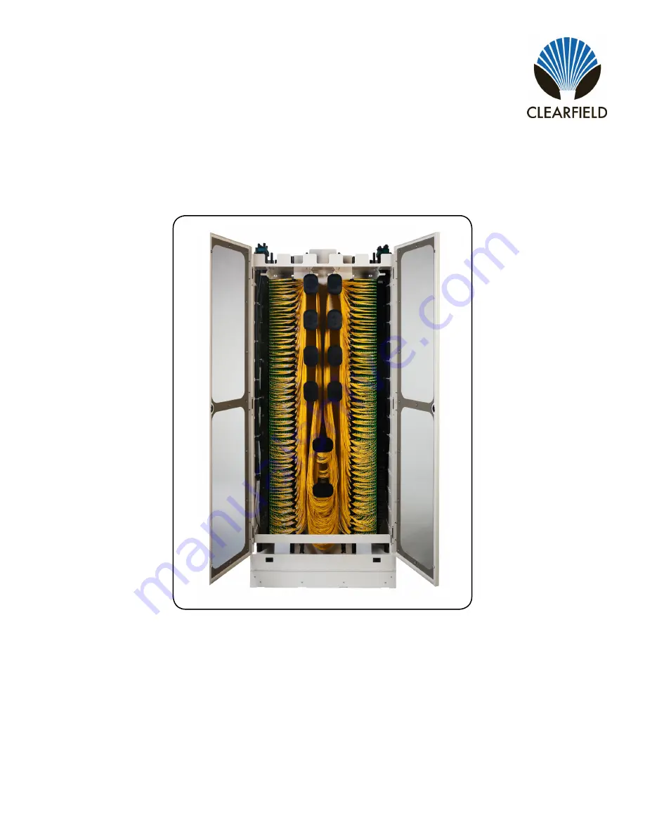
FxHD Frame
Installation Manual
______________________________________________________
Manual 014815 REV C - Feb 2018
Page 1: ...FieldSmart FxHD Frame Installation Manual _______________________________________________________ Manual 014815 REV C Feb 2018 ...
Page 2: ...ontents Application 3 Description 3 Technical Specifications 3 FxHD Frame Installation 4 Standard Floor Installation 8 Raised Floor Installation 10 FxHD Frame Installation Continued 14 Adjusting the Doors 16 Clearview Blue Patch Splice Installation in FxHD 17 Clearview Blue Patch Only Installation in FxHD 19 Jumper Routing Guide 21 Connector Cleaning Procedure 30 Standard Warranty 33 Proprietary N...
Page 3: ...ame The FxHD can be placed against a wall cage in data center collocation environments or installed back to back User defined Clearview building blocks configured to exact port count specifications can be deployed in seconds with Smart Connect tool less fasteners Clearview Blue Cassettes simply slide into building block assemblies with a hard stop feature ensuring perfect alignment every time Addi...
Page 4: ...This should include 1 Bulkhead 2 Base Assembly Base Plate and Lower Trough 3 Isolation Pad 4 2 Doors 5 2 End Guards 6 Top Trough Assembly 7 Grounding Bar 8 Miscellaneous Hardware Note The FxHD Frame system comes in two main configurations patch only and patch and splice The difference is that the patch only main bulkhead does NOT come with the ganging brackets install on the bulkhead as the gangin...
Page 5: ...e assembly by the center portion on both ends to prevent bending the bulkhead On the reverse side of the bulkhead are radius limiters Be very careful setting this aside Do not drag on the floor Locate and remove the box labeled Base Assembly Also remove the isolation pad and the floor mounting hardware and set aside Separate the base plate from the lower trough by removing the screws from the fron...
Page 6: ...into place as shown Note The black plastic Building Brackets shown are not included with a Patch Only Frame Attach the bulkhead to the base with the provided bolts from the rear of the frame Do not fully tighten the bolts at this point Note If the frame is going to be mounted against a wall or other frame you must tighten these bolts before putting the frame into its final position Locate the boxe...
Page 7: ...018 Locate the box labeled Upper Trough Inside the box will be a second box labeled End guard Support Locate this box and set aside The upper trough is installed at the top of the frame as shown The upper trough is mounted using the provided screws The mounting locations are shown below Install two screws on each side from the top down two on each side through the end guard and two in front undern...
Page 8: ...x 2 Note If for some reason you have trouble drilling the 5 8 hole we recommend first drilling a 1 4 pilot hole before drilling out to 5 8 Thoroughly clean the dust from each hole using an air blowout or vacuum device Note To not degrade the anchor s installed performance any unused anchor holes or other nearby holes in the concrete within 3 must be filled with an epoxy filler pour stone or equiva...
Page 9: ...ce aligned tap each anchor washer assembly until it is seated in the hole and firmly against the 2 square washer Pre tighten each anchor with a socket wrench or box end wrench do not use an open end wrench which could easily slip off and cause injury Before final tightening ensure that the frame is properly aligned in the row and with any adjacent frames Torque each anchor to 60 ft lbs Note When u...
Page 10: ...quired is a raised floor mounting kit Clearfield P N 011236 1 1 2 13 Hex Nut Qty 8 2 1 2 Lock Washer Qty 4 3 1 2 Flat Washer Qty 4 4 1 2 13 x 30 Threaded Rod Qty 4 5 Hilti HDI 1 2 Anchor Qty 4 6 1 4 x 2 Flatwasher 515 Hole Qty 8 7 Split Tubing 30 Qty 4 Screw Sequence for Floor Screw Sequence for Frame Note Clearfield recommends installing the anchors directly into the concrete floor Note It is imp...
Page 11: ...erpendicular to the floor tap on the end firmly The goal is to make a mark on the concrete floor visible enough to see where the 4 holes should be drilled Once the concrete floor is marked remove the threaded rods and floor panels Using a 5 8 masonry bit drill the four required holes to a minimum depth of 2 approx 50mm Note If for some reason you have trouble drilling the 5 8 hole we recommend fir...
Page 12: ...rk with a permanent marker Remove the rods and cut each rod at the mark Remove the floor panels Before installing rods back into the floor place a nut and then a washer on the threaded rods Take the rod and install it into the anchor installed in the floor Tighten the nut down to secure the rod into the floor Tighten each bolt to 65 ft lbs 10 0 ft lbs The anchor will expand and secure itself to th...
Page 13: ...l they make contact with the panel Put isolation pad into place isolation pad may look different than example Lift the frame into place Place the square washers onto each rod Align the edges of the 2 square washer parallel with the slots in the frame base to obtain the maximum material overlap Install the isolation washers packaged with the isolation pad onto each rod Install the remaining hardwar...
Page 14: ... the frame into place per the previous floor mounting instructions of this manual Once the frame system is secured to the floor place the lower trough on the base and using the 4 screws removed earlier secure the trough to the base You can now add the end guard support bars Retrieve the box marked End Guard Support Install the support by sliding into place as shown aligning the pins and sockets an...
Page 15: ... SeeClearfield com techsupport clfd net Manual 014815 REV C Feb 2018 The doors will slide onto the end guards aligning the pins and sockets of the hinges as shown Doors need to be open to 90 degrees to slide in easily Note The doors will serve as your front protection The bolts on the back of the frame can now be tightened into place End Guard Door ...
Page 16: ...ap approximately 1 8 from the top of the doors to the bottom This can be done by adjusting the screws which hold the hinges to the end guards Start with the screw in the center of the slot as most applications will not need adjust ment afterward After the horizontal adjustments have been made adjust the doors to be even vertically This is done by locking down the higher door and then adjusting the...
Page 17: ...arfield recommends you install the cassettes into the frame system before prepping your incoming fiber cable This will help ensure the proper buffer tube prep lengths when measuring them during prep Start by prepping and removing the jacket from the last 20 feet of the OSP cable Locate the green cable clamp shells and corresponding mounting screws from the ship along hardware Determine which clamp...
Page 18: ... mark the buffer tubes with a marker For a group of 12 buffer tubes a good rule of thumb is to make the loop as long as the 12 cassettes you are splicing After placing a mark on the top buffer tube begin marking each buffer tube 1 shorter for a neat slack loop Note This loop can be smaller toward the bottom of the frame Splice the cassettes one at a time and store the slack up to the mark shown pe...
Page 19: ... cable until the cassette block is in place Now insert the cassette block into the desired location with the block almost touching the back of the frame If applicable slide the block up to engage the one above then slide it back in the frame to lock into place Each square screw will then need to be pressed until it clicks into place to fully secure the block Note The actual number of square mounti...
Page 20: ... kit to at least one side of the clamp Use the included mounting screws to fasten the clamp shells and cable to the clamping location as shown It is best to start by clamping cables in the rear of the frame first and work toward the front Note As the frame gets closer to full the breakouts will be mounted lower and lower in the frame The FxHD comes with optional bridge lances for cable organizatio...
Page 21: ...______________________________________ Installation Manual Direct 763 476 6866 National 800 422 2537 www SeeClearfield com techsupport clfd net Manual 014815 REV C Feb 2018 Jumper Routing Guide Zone 1 to 2 1 2 Zone 1 to 1 1 2 Single Frame Routing ...
Page 22: ...chsupport clfd net 22 FieldSmart FxHD Frame Installation Manual __________________________________________________________ Manual 014815 REV C Feb 2018 Two Frames Back to Back Upper Pass Through Front to back cable pass through 1 2 3 4 Zone 2 to 3 Zone 2 to 4 1 2 3 4 ...
Page 23: ..._________________ Installation Manual Direct 763 476 6866 National 800 422 2537 www SeeClearfield com techsupport clfd net Manual 014815 REV C Feb 2018 Two Frames Back to Back Upper Pass Through Front to back cable pass through 1 2 3 4 Zone 1 to 4 Zone 1 to 3 1 2 3 4 ...
Page 24: ...chsupport clfd net 24 FieldSmart FxHD Frame Installation Manual __________________________________________________________ Manual 014815 REV C Feb 2018 Two Frames Back to Back Lower Pass Through Front to back cable pass through 1 2 3 4 Zone 2 to 4 1 2 3 4 Zone 2 to 3 ...
Page 25: ..._________________ Installation Manual Direct 763 476 6866 National 800 422 2537 www SeeClearfield com techsupport clfd net Manual 014815 REV C Feb 2018 Two Frames Back to Back Lower Pass Through Front to back cable pass through 1 2 3 4 Zone 1 to 3 1 2 3 4 Zone 1 to 4 ...
Page 26: ...eClearfield com techsupport clfd net 26 FieldSmart FxHD Frame Installation Manual __________________________________________________________ Manual 014815 REV C Feb 2018 Multiple Bays Side by Side Lower Trough 1 2 3 4 Zone 1 to 3 1 2 3 4 Zone 1 to 4 ...
Page 27: ...___________________________________ Installation Manual Direct 763 476 6866 National 800 422 2537 www SeeClearfield com techsupport clfd net Manual 014815 REV C Feb 2018 Multiple Bays Side by Side Lower Trough 1 2 3 4 Zone 2 to 4 1 2 3 4 Zone 2 to 3 ...
Page 28: ...eClearfield com techsupport clfd net 28 FieldSmart FxHD Frame Installation Manual __________________________________________________________ Manual 014815 REV C Feb 2018 Multiple Bays Side by Side Upper Trough 1 2 3 4 Zone 1 to 4 1 2 3 Zone 1 to 3 4 ...
Page 29: ...___________________________________ Installation Manual Direct 763 476 6866 National 800 422 2537 www SeeClearfield com techsupport clfd net Manual 014815 REV C Feb 2018 Multiple Bays Side by Side Upper Trough 1 2 3 4 Zone 2 to 3 1 2 3 Zone 2 to 4 4 ...
Page 30: ...nd techniques ensures a clean end face no matter the type of contamination These are Clearfield recommended products application Use the product you feel will complete your cleaning procedures Create a best practice for your company and follow those procedures Note It is NOT recommended to use IPA to clean the end face Cleaning the end face but not just the end face Place one wiping paper on QbE 2...
Page 31: ...circle around 2 3 times and remove Turn swab to dry side and repeat Figure 5 Cleaning the mate through a bulkhead adapter AND the adapter itself Lightly moisten the fiber optic swab 2 5mm 38542F or 1 25mm 38040 by spotting a small amount about 1 of Electro Wash PX or Elec tro Wash MX pen onto the QBE 2 Hold the tip of the swab onto the wetted area and hold for a count of 1 2 3 4 5 Insert the swab ...
Page 32: ...ng the container or end face Angle is correct when no drag is left on the end face Figure 2 Male Connector Lightly moisten the fiber optic swab CC505F like above moistening 1 side Place swab wet side down at one end of connector end face and draw across in a diagonal sweep ie from fiber 1 up and across to fiber 12 Turn swab over to dry and draw back from fiber 12 to fiber 1 Figure 3 BEFORE cleanin...
Page 33: ...n of Clearfield Inc shall constitute the exclusive sole remedy for a breach of this limited warranty Clearfield shall not be liable under any circumstances for any special consequential incidental punitive or exemplary damages arising out of or in any way connected with the product or with agreement to sell product to buyer including but not limited to damages for lost profits loss of use or for a...
Page 34: ...pplied Every effort has been made to keep the information contained in this document current and accurate as of the date of publication or revision However no guarantee is given or implied that the document is error free or that it is accurate with regard to any specification Technical Support Clearfield Inc can be contacted for any issues that arise with the supplied product If you need to return...