© 2022
Order #XXXXX
Locked layer contains
placeholder marks.
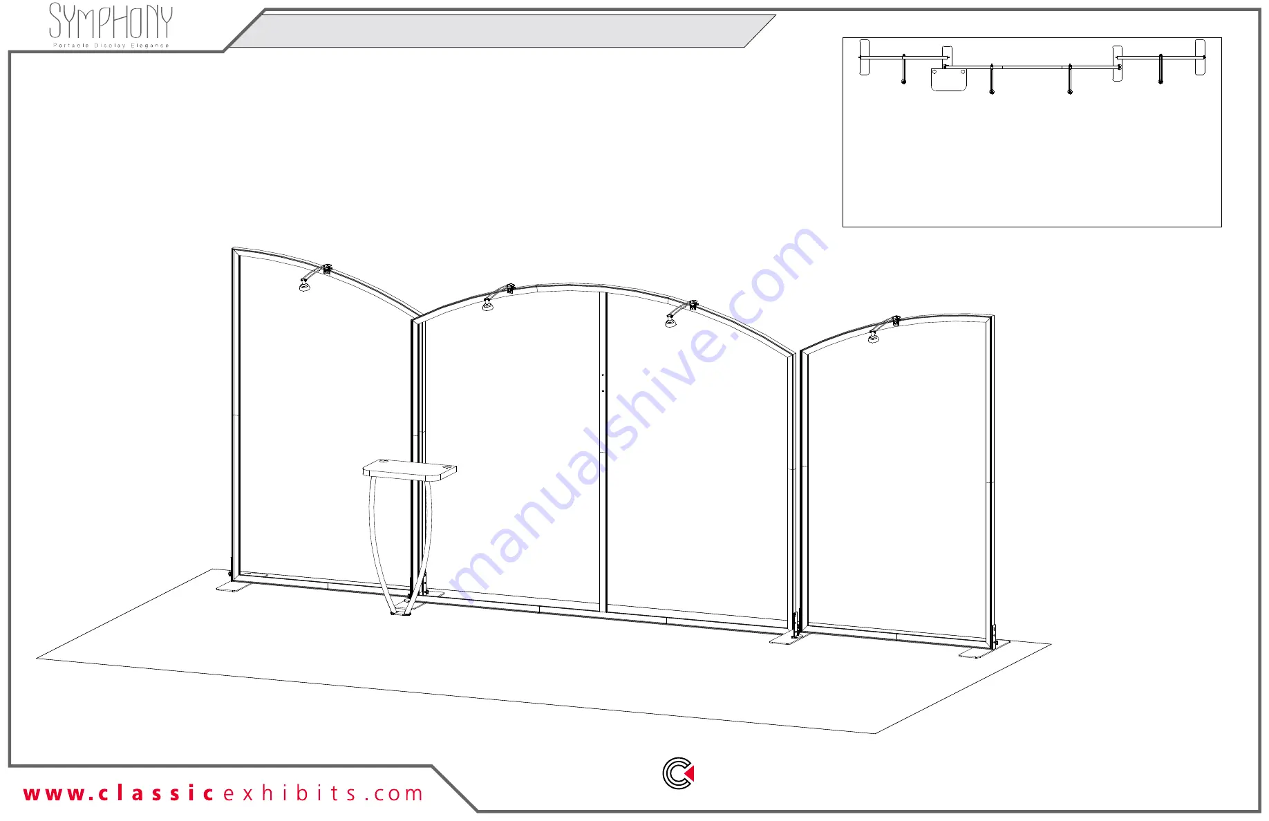
Plan View
10’
20’
Perspective View
SYK-2019 - 10’ x 20’ Portable Display
If you would like to tell us about your experience with your setup instructions please email us at
[email protected]
SETUP INSTRUCTIONS
REV 7/2022


