w w w . c l a s s i c
e x h i b i t s . c o m
Step 1
Page 1 of 6
866.652.2100
© 2011
WHEN DISASSEMBLING ALUMINUM EXTRUSION, TIGHTEN ALL
SETSCREWS AND LOCKS TO PREVENT LOSS DURING SHIPPING
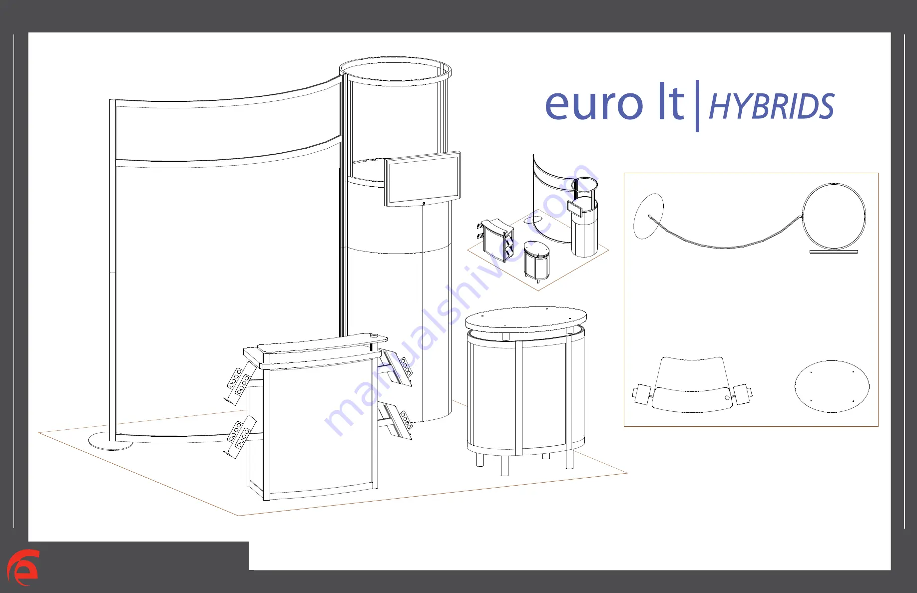
Order #XXXXX - General Layout
10’
Plan View
Page 1: ...s s i c e x h i b i t s c o m Step 1 Page 1 of 6 866 652 2100 2011 WHEN DISASSEMBLING ALUMINUM EXTRUSION TIGHTEN ALL SETSCREWS AND LOCKS TO PREVENT LOSS DURING SHIPPING Order XXXXX General Layout 10 1...
Page 2: ...s see below in RED This is VERY IMPORTANT Cleaning and Packing Your Display 1 Use care when cleaning aluminum extrusion or acrylic inserts Use only non abrasive cleaners 2 When cleaning laminate inser...
Page 3: ...el 1 Item Number 1 2 3 4 5 6 Description 47 5 h x 15 r Curve Panel 47 5 h x 15 r Curve Panel 47 5 h 180 Connector 47 5 h x 15 r Curve Panel 47 5 h x 15 r Curve Panel 47 5 h 180 Connector Steps Assembl...
Page 4: ...s togeter by starting at panel 1 1 2 2 2 4 4 4 Extrusion 3 Connector 3 Extrusion 3 Connector 3 Extrusion 3 Connector 3 Note Extrusion 3 and connectors 3 must stay assembled Item Number 1 2 3 4 5 6 Des...
Page 5: ...ed Attach pins to lower inner side of window frame where indicated then set shelf atop pins Steps Assemble panels together by starting at panel 2 and continue in numerical order Indicates Pin Location...
Page 6: ...tion Mitre cut SEG Extrusion Profile Graphic Removal To remove the graphicfrom the frame locate the fabric pull tab Gently pull up on the tab to remove the fabric Step 1 Insert corner A Turn edge of g...
Page 7: ...11 and 12 as shown 2 Place inserts and attach door where indicated 3 Attach upper horizonal extrusions 13 14 and 15 between vertical extrusions 9 10 11 and 12 as shown 4 Velcro internal shelf support...
Page 8: ...nserts and attach door where indicated 3 Attach upper horizontal extrusions 18 and 19 between vertical extrusions 17 22 and 23 as shown 4 Attach extrusion legs to underside of floor 5 Attach short pin...