background image

4

GENERAL MAINTENANCE

AERATOR MAINTENANCE

TO KEEP THE AERATOR IN GOOD
OPERATING CONDITION, PERFORM 
THE FOLLOWING:

When replacement parts are required, use genuine
Classen parts or parts with equivalent characteristics
including type, strength, and material. Failure to do so
may result in product malfunction and possible injury
to the operator and/or bystanders.

Any warning decal that becomes illegible should be
replaced immediately. (See Pg. 5.)

Do not operate equipment without shield(s) in place.
Do not make any adjustments or perform any
maintenance while the engine is running.

Thoroughly clean all tines inside and out when
aerating is completed and apply a light coat of oil to
prevent rust on tines.

Always lubricate Aerator each time it is put into
service. Wipe off lubrication fittings before and after
each lubrication. The number of lubrication fittings
vary depending on model of Aerator. 

Model CA-18

- Qty 2, one in each rear wheel assembly.

Models TA-19D/TA-26D

(water drum models) - Qty 3, one in

each rear wheel assembly and one on the idler/clutch arm pivot
bearing. (See Fig. 2.) 

Models TA-19/TA-26

(front tire models) - Qty. 5, one in each

wheel assembly and one on the idler/clutch arm pivot bearing.
(See Fig. 2.)

Models TA-17D/TA-25D

- Qty. 4, one in each wheel assembly

and one in each idler/clutch arm pivot bearing. (See Fig. 2.)

Check roller chain(s) for tightness. Follow these steps:

Model CA-18

(See Fig.3.)

1.

Disconnect spark plug.

2.

Take off pulley guard by removing two nuts and 
lock washers.

3.

Loosen nut (B) by turning counter-clockwise until nut
comes in contact with head of bolt (A).

4.

Tighten bolt (A) until chain is tight between front axle
sprocket (D) and tine assembly sprocket (E). 

(See Note Opposite Page)

5.

Retighten nut (B) by turning clockwise against 
lock washer (C).

6.

Replace pulley guard, nuts and lock washers and
retighten nuts.

Pulley Guard

Fig. 2

Idler Clutch Arm

(Right Side)

Keep drive belt(s) free of oil and dirt.

Models TA-17D/TA-25D

- If belts slip due to normal belt

stretch, engine can be adjusted forward within slotted holes to
tighten belts.

Check roller chain(s) for wear. Apply a light coat of
No. 30 oil or penetrating chain lubricant to keep the
chain(s) clean and in proper running order.

A

Fig. 3

B

C

D

E

Fig. 4

Main Frame Top Flat (Left Side)

Main Frame (Left Side)

Model TA-17/TA-19/TA-25/TA-26

(See Fig. 4.)

1.

Disconnect spark plug.

2.

Take off pulley guard (see Fig. 2) by removing bolts,
etc. which attach it to the frame.

3.

Loosen the bolts, nuts, lock washers, and flat washers
(Key 4) to allow movement of the pillow block
bearings only (Key 5). Loosen nuts only, do 
not remove.

4.

Loosen and unthread the two 5/16'' nuts (Key 2) down
to top of chain tightening bracket (Key 3).

5.

Turn the tap bolts (Key 1) evenly clockwise so jack
shaft stays level with frame until chain(s) is/are tight.

Summary of Contents for 48-RT

Page 1: ...ERATOR S MANUAL AERATOR MODELS CA 18 Compact Aerator TA 17D TA 25D Split Drive Aerators TA 19D TA 26D Turf Aerators 48 RT 60 RT 72 RT Tow Aerators 1028 Street Road P O Box 38 Southampton PA 18966 U S...

Page 2: ...RATOR 6 Parts Main Frame 6 Parts Power Train and Tine Rotor Assembly 7 Parts Handle and Control 8 TA 17D SPLIT DRIVE AERATOR 9 Parts Main Frame 9 Parts Power Train Assembly 10 Parts Handle and Control...

Page 3: ...tor READ THIS MANUAL Read this manual carefully in its entirety It contains safety operating maintenance and adjustment instructions for your Aerator By following the operating and maintenance instruc...

Page 4: ...make repairs before restarting and operating 15 Stop the engine a whenever you leave the unit b before refueling and c before clearing blockages 16 Reduce the throttle setting during engine run out an...

Page 5: ...orting from one work area to another by lifting up on lowering handle see Fig 1 2 Aerator can be transported with the engine running or with the engine off WARNING CAUTION TO AVOID INJURY DO NOT PLACE...

Page 6: ...er clutch arm pivot bearing See Fig 2 Check roller chain s for tightness Follow these steps Model CA 18 See Fig 3 1 Disconnect spark plug 2 Take off pulley guard by removing two nuts and lock washers...

Page 7: ...HT STORAGE INSTRUCTIONS Before the Aerator is put into storage for any period exceeding 30 days the following steps should be taken 1 Drain all fuel from fuel tank and fuel lines 2 Start engine and ru...

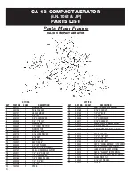
Page 8: ...100250 2 SPRING Parts Main Frame CA 18 COMPACT AERATOR S N 1062 UP PARTS LIST QTY PER KEY PART NO SHEET DESCRIPTION 24 400141 1 ARM R H REAR AXLE SUPPORT 25 500169 2 5 16 LOCK NUT 26 500149 2 1 2 x 2...

Page 9: ...SPROCKET 40 B27 x 1 22 500003 1 1 4 x 7 8 HALF MOON KEY 23 300073 1 SPACER TINE SHAFT 24 100248 2 BEARING PLATEDFLANGEw COLLAR 1 2BOLT 25 100254 1 CHAIN 40 x 109 PITCH 26 100025 1 CONNECTING LINK 27...

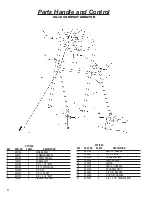
Page 10: ...3 8 NUT 8 500041 27 3 8 LOCK NUT 9 500178 2 3 8 x 3 1 4 BOLT 10 100251 2 HANDLE LOCK RING CA 18 COMPACT AERATOR QTY PER KEY PART NO SHEET DESCRIPTION 11 400130 1 ARM L H LINKAGE 12 500091 4 3 8 x 2 B...

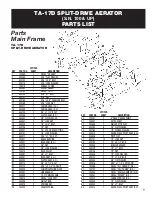
Page 11: ...LT 32 500114 4 5 16 x 2 1 4 TAP BOLT 33 300049 4 CHAIN TIGHTENING PLATE 34 300007 2 LINKAGE ARM 35 400080 1 TA 17D MAIN FRAME 36 100074 3 DECAL CLASSEN 37 400056 1 WEIGHT BAR 38 400015 2 SPRING ARM 39...

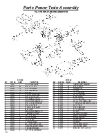
Page 12: ...132 2 1 OUTSIDE SPACER 20 200009 2 40 x 36 SPROCKET HUB 21 300011 2 OUTSIDE DRUM SHAFT SPACER 22 300131 2 2 MACHINERY WASHER 23 500003 2 1 4 x 7 8 HALF MOON KEY QTY PER KEY PART NO SHEET DESCRIPTION 2...

Page 13: ...091 1 CONTROL HANDLE R H 7 500041 9 3 8 LOCK NUT 8 500130 6 3 8 LOCK WASHER 9 500129 6 3 8 NUT 10 100034 2 CLUTCH CABLE SPRING QTY PER KEY PART NO SHEET DESCRIPTION 11 400018 1 MAIN HANDLE 12 500043 6...

Page 14: ...4 4 5 16 x 2 1 4 TAP BOLT 33 300049 4 CHAIN TIGHTENING PLATE 34 300007 2 LINKAGE ARM 35 400079 1 TA 25D MAIN FRAME 36 100074 3 DECAL CLASSEN 37 400057 1 WEIGHT BAR 38 400015 2 SPRING ARM 39 100040 2 F...

Page 15: ...500131 8 1 2 LOCK NUT 19 300011 2 OUTSIDE DRUM SHAFT SPACER 20 200009 2 40 x 36 SPROCKET HUB 21 300131 2 2 MACHINERY WASHER 22 500003 2 1 4 x 7 8 HALF MOON KEY QTY PER KEY PART NO SHEET DESCRIPTION 23...

Page 16: ...090 1 CONTROL HANDLE R H 7 500041 9 3 8 LOCK NUT 8 500130 6 3 8 LOCK WASHER 9 500129 6 3 8 NUT 10 100034 2 CLUTCH CABLE SPRING QTY PER KEY PART NO SHEET DESCRIPTION 11 400028 1 MAIN HANDLE 12 500043 6...

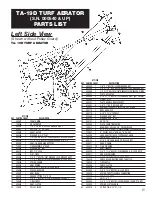
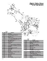
Page 17: ...HER 2 NUTS 29 300037 1 PLATE ADJUSTER 30 500005 4 5 16 X 1 1 2 BOLT W LOCK WASHER NUT NOT SHOWN 31 300009 1 WEIGHT STOP 32 _ 300071 1 PLATE HANDLE BRACE GUSSET 33 500051 6 3 8 X 1 BOLT W LOCK NUT 34 1...

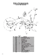
Page 18: ...2 FLAT WASHERS LOCK NUT 24 500042 1 WASHER 3 8 FLAT 25 500051 6 3 8 X 1 BOLT W LOCK NUT 26 100032 30 TINE PLUGGING 27 400071 1 GUARD CHAIN 28 300007 2 ARM LINKAGE 29 400017 1 HANDLE LOWERING 30 500049...

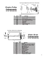
Page 19: ...ONDA QTY PER KEY PART NO SHEET DESCRIPTION 1 700009 1 AXLE DRUM 2 100004 4 BEARING w ECCENTRIC COLLAR 1 PILLOW BLOCK 3 500040 8 1 2 x 1 3 4 BOLT w FLAT WASHER LOCK NUT 4 100083 1 WASHER SMALL STEEL 5...

Page 20: ...1 CONNECTING LINK 40 7 100032 30 TINE PLUGGING 8 500128 60 5 16 x 1 1 2 BOLT w LOCK NUT 9 500040 8 1 2 x 1 3 4 BOLT w FLAT LOCK NUT 10 200009 1 SPROCKET w 1 HUB 40 x 36 11 100004 4 BEARING w ECCENTRI...

Page 21: ...2 BOLTW 2 FLATWASHERS LOCKWASHER 2 NUTS 29 300037 1 PLATE ADJUSTER 30 500005 4 5 16 X 1 1 2 BOLT W LOCK WASHER NUT NOT SHOWN 31 300009 1 WEIGHT STOP 32 300071 1 PLATE HANDLE BRACE GUSSET 33 500051 6...

Page 22: ...H 23 500107 1 3 8 X 1 BOLT W 2 FLAT WASHERS LOCK NUT 24 500042 1 WASHER 3 8 FLAT 25 500051 6 3 8 X 1 BOLT W LOCK NUT 26 100032 42 TINE PLUGGING 27 400071 1 GUARD CHAIN 28 300007 2 ARM LINKAGE 29 40002...

Page 23: ...ONDA QTY PER KEY PART NO SHEET DESCRIPTION 1 700010 1 AXLE DRUM 2 100004 4 BEARING w ECCENTRIC COLLAR 1 PILLOW BLOCK 3 500040 8 1 2 x 1 3 4 BOLT w FLAT WASHER LOCK NUT 4 100083 1 WASHER SMALL STEEL 5...

Page 24: ...1 CONNECTING LINK 40 7 100032 42 TINE PLUGGING 8 500128 84 5 16 x 1 1 2 BOLT w LOCK NUT 9 500040 8 1 2 x 1 3 4 BOLT w FLAT LOCK NUT 10 200009 1 SPROCKET w 1 HUB 40 x 36 11 100004 4 BEARING w ECCENTRI...

Page 25: ...00159 8 3 8 x 3 BOLT 18 100032 48 TINE Parts Main Frame 48 RT TOW AERATOR S N 000337 UP PARTS LIST QTY PER KEY PART NO SHEET DESCRIPTION 19 700026 2 TINE SHAFT 20 300106 2 TINE END SPACER 21 300058 2...

Page 26: ...59 8 3 8 x 3 BOLT 18 100032 60 TINE Parts Main Frame 60 RT TOW AERATOR S N 000161 UP PARTS LIST QTY PER KEY PART NO SHEET DESCRIPTION 19 700027 2 TINE SHAFT 20 300106 2 TINE END SPACER 21 300058 2 CEN...

Page 27: ...159 8 3 8 x 3 BOLT 18 100032 72 TINE Parts Main Frame 72 RT TOW AERATOR S N 144 UP PARTS LIST QTY PER KEY PART NO SHEET DESCRIPTION 19 700029 2 TINE SHAFT 20 300106 2 TINE END SPACER 21 300058 2 CENTE...

Page 28: ...chantability and fitness for a particular purpose are limited to two years from the date of purchase and to the extent permitted by law any and all implied warranties are excluded The above remedy of...

Page 29: ......

Page 30: ...ility for variations which may be evident in the actual specifications of its products and the statements and descriptions contained in this publication COMPACT AERATORS CA 18H CA 18B SPLIT DRIVE AERA...

Reviews: