Scrub System
49
Service Manual – Clarke CA30 20B and 17E
Motor Carbon Brushes (Battery Model)
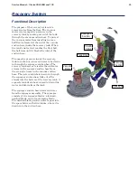
The motor brushes provide an electrical connection to the spinning rotor. The motor contains 4 brushes. The
brushes will wear over time and must be replaced. The copper strips on the rotor that the brushes contact
are called the commutator bars, and these are connected to the individual windings on the rotor.
1. Remove the
Scrub Deck
described on page 46.
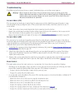
Caution:
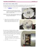
The position of the end bell (top cap) of the motor
is critical to the operation and clearances within the
motor. Do not remove the end bell. Do not loosen the
screws securing the end bell.
Caution: Take care to not drop any objects into the motor. The
motor contains permanent magnets, which may make
retrieving metal objects difficult.
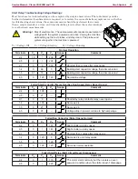
2. Remove the two screws
(B)
that secure the brush
shield
(A)
to the motor, and remove the shield.
Take care when loosening the last screw, as the
shield is springy and may fling the last screw.
The components of the brush mechanism are shown.
There are 4 of these mechanisms spaced around the
motor. The coiled spring
(D)
presses against the top of the
carbon brush
(C)
, pressing it against the commutator bars
of the rotor. The carbon brush has a flexible, embedded
wire that connects to the incoming power connections
(E)
.
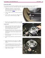
3. Remove the terminal nut
(E)
.
•
Take care not to bend the terminal. Hold the
terminal from twisting as you loosen the nut.
•
Take care to not drop the nut (or anything else) into
the motor.
4. Remove the brush wire from the terminal.
DO NOT
REMOVE
A
B
D
C
E

