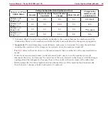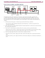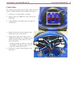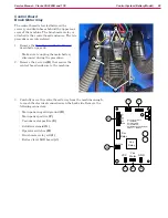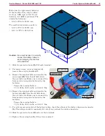
Control System (Battery Model)
22
Service Manual – Clarke CA30 20B and 17E
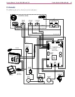
Schematic
The following shows the electrical controls schematic.
SOLUTION
SWITCH
POWER
SWITCH
VACUUM
SWITCH
Brush Switches
BRUSH
MOTOR
CONTROL PANEL
BRUSH
RELAY
VACUUM
MOTOR
SOLUTION
SOLENOID
Scrub Active S2
Vacuum S3
+Common
Solution S4
7
7
Hour Meter
Scrub Active
GND
Vac
Motor
VCC
COM
S2
S3
S4
C-
C+
SOLUTION
Vac
Relay
Solution
Relay
COM = C+ = Common
C- = Machine Enable (Charger)
S4 = Solution SW
S3 = Vacuum SW
S2 = Scrub SW
C+ = Com = Common
Battery Meter
BATTERY
CHARGER
30A
30A
BATTERY
DISCONNECT
+Common
Machine Enable
MACHINE ENABLE
NORMALLY
CLOSED RELAY
BRUSH
CIRCUIT
BREAKER
Batt +
Switched Batt -
Batt (+)
Batt (-)
Switched Batt -
Batt +
+Common


