


20
Service Manual – Clarke CA30 20B and 17E
Control System (Battery Model)
Functional Description
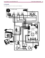
The CA30 20B utilizes a main machine controller to turn on various machine functions. It receives operator
switch inputs, and activates various solenoids and components. Each of the machine components is described
below. Refer to the machine
Schematic
on
page 22
for details.
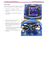
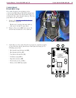
Control Panel
The control panel (display) provides the main operator interface for the machine. It provides battery status
and contains the switches for operating the machine.
Battery Indicator
Solution Switch
Battery Charge Level
Main Power Switch
Hour Meter
Vacuum Switch
Main Power Switch
The main power switch controls power to the main control board and the hour meter. For the hour meter,
both the positive and negative power leads are switched. For the control board, only the negative power
lead is switched. Positive power is always present at the control board, but passes through a 30-amp circuit
breaker.
This arrangement reduces the total amperage flowing through the main power switch. The power consumed
by the brush motor and vacuum motor do not pass through this switch. Only their control signal power
passes through this switch. This reduces the likelihood of the switch contacts being damaged by high
amperage current flow.