OPERATION & MAINTENANCE
INSTRUCTIONS
ORIGINAL INSTRUCTIONS GC01/18 REV 5
STARTER/CHARGER
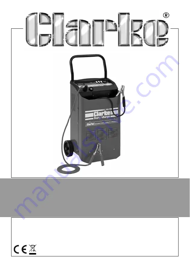
MODEL NO: BC520P
PART NO: 6261082
Page 1: ...OPERATION MAINTENANCE INSTRUCTIONS ORIGINAL INSTRUCTIONS GC01 18 REV 5 STARTER CHARGER MODEL NO BC520P PART NO 6261082...
Page 2: ...th in any way or not used for the purpose for which it was intended Faulty goods should be returned to their place of purchase no product can be returned to us without prior permission This guarantee...
Page 3: ...mensions D x W x H 320 x 490 x 730 Weight 24 kg Open circuit protection 200A Lamellar Fuse IP Rating IP20 Operating Temperature Range 0 to 40 C Input Voltage 50Hz 230 V AC Duty Cycle Starting 10 sec O...
Page 4: ...with reduced physical sensory or mental capabilities or lack of experience and knowledge unless they have been given supervision or instruction concerning use of the charger starter by a person respo...
Page 5: ...ps WARNING THIS APPLIANCE MUST BE EARTHED IMPORTANT The wires in this mains lead are coloured in accordance with the following code GREEN AND YELLOW EARTH E BLUE NEUTRAL N BROWN LIVE L As the colours...
Page 6: ...unctions A MAX MIN switch allows for charging at two different rates and the unit is provided with a two position Power Setting switch which allows for even greater control of charge rates as displaye...
Page 7: ...r to any electronically controlled system fitted to the vehicle such as engine management system anti theft alarm alternator etc 2 Check that the ON OFF switch on the unit is in the OFF position 3 Con...
Page 8: ...0 hours If a low amperage reading 2 amps or less is seen on the gauge at either the MIN or MAX setting This may indicate that the battery is either a already fully charged or b at the end of its usefu...
Page 9: ...an assistant to switch the CHARGE BOOST START switch to BOOST START position IMPORTANT If the engine fails to start almost immediately you MUST return the CHARGE BOOST START switch to CHARGE position...
Page 10: ...rrosion from the clamps with a solution of water and baking soda 3 Examine the leads at regular intervals for damage and have them replaced if necessary STORAGE 1 Wind up the connecting leads and powe...
Page 11: ...11 Parts Service 020 8988 7400 E mail Parts clarkeinternational com or Service clarkeinternational com DECLARATION OF CONFORMITY...
Page 12: ...Handle 15 Axle L 415 3 Front Frame 16 Lower Panel 4 Ammeter 50A Start 17 Wheel 5 Female Dinse Plug 18 Transformer Starter 6 Clamps 120A 19 n a 7 Black Charge Cable 20 Front Control Panel 8 Fuse 200A 2...
Page 13: ...13 Parts Service 020 8988 7400 E mail Parts clarkeinternational com or Service clarkeinternational com PARTS DIAGRAM...
Page 14: ...14 Parts Service 020 8988 7400 E mail Parts clarkeinternational com or Service clarkeinternational com CIRCUIT DIAGRAM...
Page 15: ...__ ___________________________________________________________________________ ___________________________________________________________________________ _____________________________________________...
Page 16: ......