CS-ZV
CitrinSolar GmbH Energie- u. Umwelttechnik • Böhmerwaldstr. 32 • D-85368 Moosburg • Tel.:+49 (0) 8761/33400 • Fax: +49 (0) 8761/334040
Page 13/48
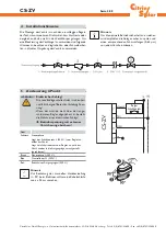
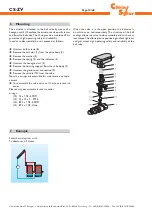
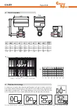
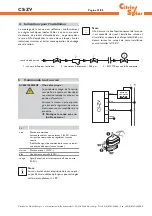
flow direction
1 - ball valves
2 - strainer
Compact- ball valve
~ 0,65 μm
3 - EMV 110..
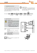
Ader
Black
Control line
If the auxiliary phase L (230 V~) is energised, the
valve opens.
If there is no control signal, the valve is put back to
its initial position (closed).
Brown
permanent live L (230 V~)
Blue
neutral line N (230V~)
Red
limit switch output signal
brown
blue
black
red
control cont.
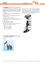
4 Installation
instructions
The installation of the valve must be carried out in accor-
dance with the approved technical regulations. Ensure ex-
cess sealing material, tape etc does not enter the valve body.
In order to avoid blocking of the valve ball, pay attention
to the following advice and avoid all soldering, or welding
processes close to the valve.
WARNING!
Electric shock!
The red limit switch lead is not insulated
and carries voltage when the valve is in the
open position!
If the actuator is not fused through the
controller connected, there is a risk of elec-
tric shock!
Î
Fuse the operating voltage with an
external pre-fuse of max. 2A!
5 On-off
control
Important note
In order to attain the maximum operating safe-
ty and reliability, it is recommended to flush the
system and to insert an appropriate strainer (0,65
μm) in front of each valve.
Note
A cable loop of about 25 cm is required for +/- 90°
manual operation.


