


3-5. Disassembly, Reassembly and Lubrication
3-23
CLP-621 & CLP-631
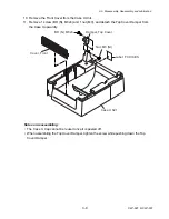
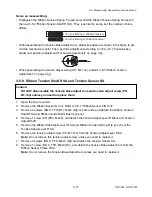
• Media-path left-edge alignment:
Align the Mechanism Unit so that the media guide end of the Head Wire Cover is aligned with
the chassis plate of the Main PCB Block (refer to 3-5-10 “Main PCB Block”).
Main PCB Block
Head Wire Cover
(Media Guide End)
Unit, Mechanism
Align.
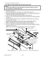
3-5-14. Platen SA
1. Open the Top Cover SA and then the Head Block.
2. While pushing the part “
A
” of the Platen SA, lift the right end a little. (See the arrow “
a
”.) Then,
remove the Platen SA from the Mechanism Unit by moving it to the right and then lift it
upwardly. (See the arrow “
b
”.)
SA, Platen
Unit, Mechanism
(Head Block)
a
b
A
Summary of Contents for CLP-621
Page 1: ...Technical Manual CLP 621 CLP 631 Thermal Transfer Barcode Label Printer JM74961 00F 1 00E 0701...
Page 2: ...CLP 621 CLP 631 ii Copyright 2007 by CITIZEN SYSTEMS JAPAN CO LTD...
Page 4: ...CHAPTER 1 SPECIFICATIONS CLP 621 CLP 631...
Page 13: ...CHAPTER 2 OPERATING PRINCIPLES CLP 621 CLP 631...
Page 73: ...CHAPTER 3 DISASSEMBLY AND MAINTENANCE CLP 621 CLP 631...
Page 126: ...CLP 621 CLP 631 CHAPTER 4 TROUBLESHOOTING...
Page 138: ...CLP 621 CLP 631 CHAPTER 5 PARTS LISTS...
Page 166: ...Chapter 5 Parts Lists CLP 621 CLP 631 5 29 DRAWING NO 7 Control Panel Unit Rev 0 4 3 2 1 5...
Page 177: ...Chapter 5 Parts Lists CLP 621 CLP 631 5 40 DRAWING NO 10 Accessories Rev 0 3 2 4 1...
Page 179: ...CHAPTER 6 CIRCUIT DIAGRAMS CLP 621 CLP 631...
Page 208: ...APPENDICES CLP 621 CLP 631...
Page 212: ...B Mounting Diagrams AP 5 CLP 621 CLP 631 Main PCB Solder side...
Page 214: ...B Mounting Diagrams AP 7 CLP 621 CLP 631 B 3 Ribbon Main PCB Parts side Solder side...
Page 217: ......


